Structurally integrated parabolic trough concentrator with combined PV and thermal receiver

a concentrator and parabolic trough technology, applied in the direction of solar heat collectors, hybrid energy generation, lighting and heating apparatus, etc., can solve the problems of significant disadvantages of being material intensive and therefore costly and uncontrollable, and less effective than a typical active cooling system, so as to reduce the cost of existing structures, offset the cost, and dissipate hea

Active Publication Date: 2017-03-28
INGRAM JOHN C
View PDF26 Cites 7 Cited by
  • Summary
  • Abstract
  • Description
  • Claims
  • Application Information

AI Technical Summary

Benefits of technology

[0011]It is an object of the invention to improve the aerodynamic performance of parabolic trough concentrators.
[0012]It is another object of the invention to provide a means of reducing and balancing the resultant aerodynamic forces due to high winds.

Problems solved by technology

While passive cooling has obvious advantages, such as simplicity and reliability, it has the significant disadvantages of being material intensive and therefore costly as well as uncontrollable, and less effective than a typical active cooling system.
Passive cooling heat sinks are typically Aluminum with high surface area that is required for natural convection heat transfer; this mass of Aluminum is a significant cost component for CPV systems.
Further cooling elements usually only add weight to a system but do not significant increase the structural strength, if at all.
In addition, because CPV systems use passive cooling to dissipate the heat from the PV cells to the atmosphere, there is little or no possibility of collecting the heat for beneficial uses.
However, it has the disadvantage that during the tracking of the sunlight either some light must be lost or the PV cell will have some dark areas, or a combination of both.
Additionally, with the dispersion of the concentrated light due to solar ray angle, imperfect specular reflection, as well as various tolerances, limit the maximum concentration.
However, in CPV systems, where great care and cost have been expended to collect the light to a narrow linear focus, cell spacing is important.
The traditional methods of tabbing solar cells to form the module into a string technically works, but with the cost of lost concentrated light and thereby efficiency.
This directly reduces the efficiency by the proportion of area covered by the buss bar since the light is reflected away from the cell and / or converted into heat.
However, this is a costly and largely unnecessary approach for many applications.
In conjunction with lift, they may also develop high torque, sufficient to damage the structure or break the constraints holding it from turning.
If aerodynamically unmodified troughs are placed on rooftops, significant damage may occur to the structure do to high speed winds.
Specifically, the following areas are poorly or have entirely not been addressed: aerodynamic issues; material intensity, which contributes to high cost; concentrated light utilization, only converting a minor portion of concentrated light to electricity for beneficial use and then throwing away the heat as opposed to collecting it for beneficial use also; using passive cooling, those few systems which use active cooling use centralized heat exchangers as opposed to each trough having its own built in radiator which is much more efficient in terms of parasitic cooling loads and is more cost effective than centralized cooling.

Method used


Image

  • Structurally integrated parabolic trough concentrator with combined PV and thermal receiver
  • Structurally integrated parabolic trough concentrator with combined PV and thermal receiver
  • Structurally integrated parabolic trough concentrator with combined PV and thermal receiver

Examples


Embodiment Construction

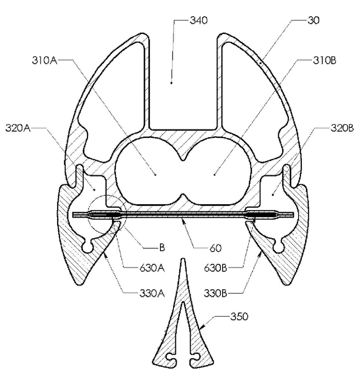
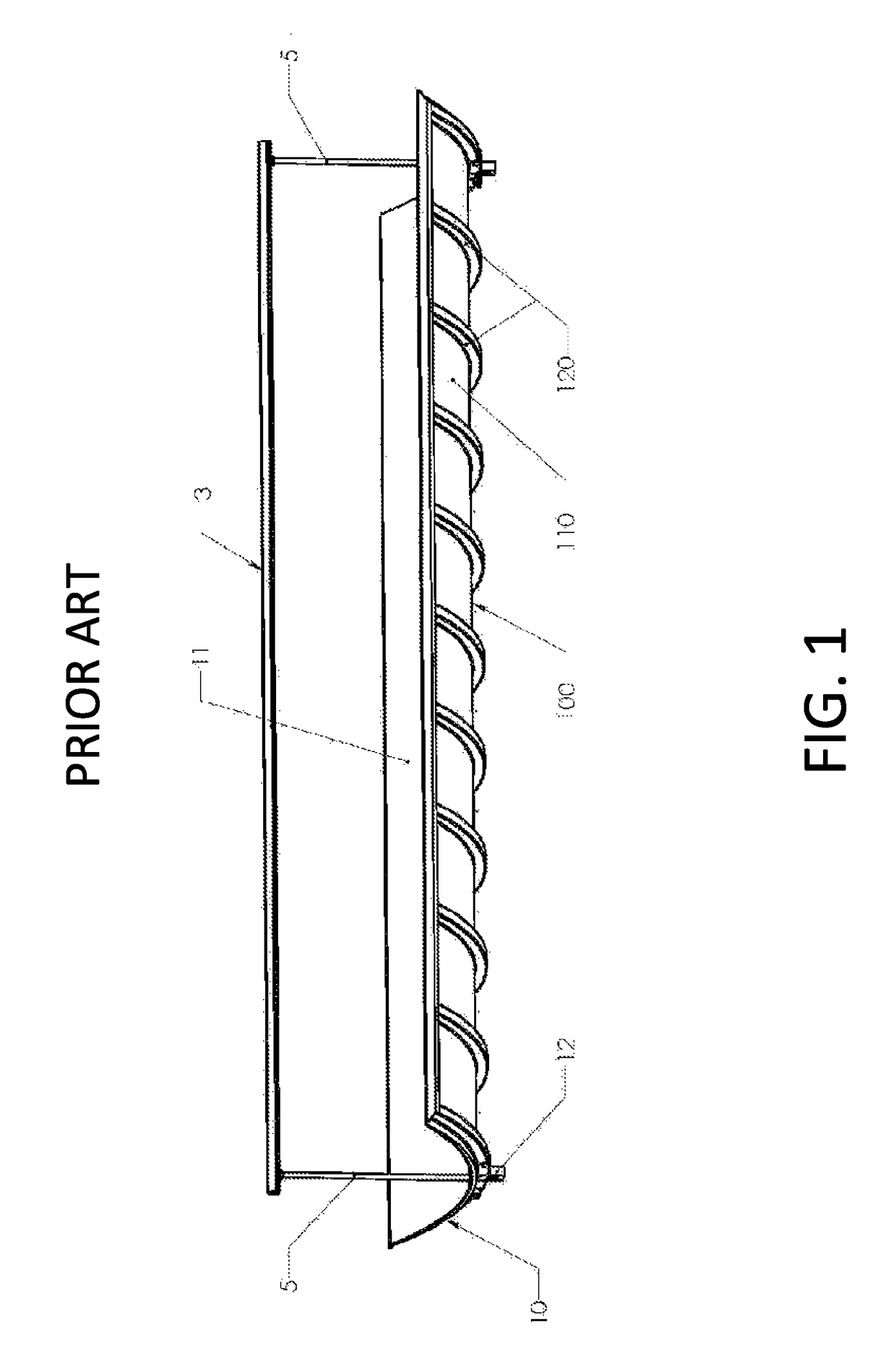
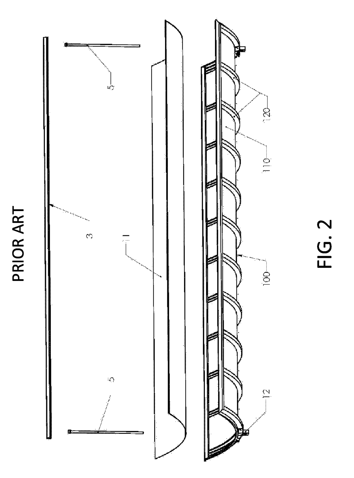
[0091]Whereas it is desirable to use parabolic troughs for concentrated solar for CPV and CPVT applications to reduce cost and increase efficiency, in general as compared to non-concentrated. It is necessary to improve on the cost and performance of the state of the art parabolic trough concentrator for both thermal and CPV applications.

[0092]This invention provides for improvements in the structure of parabolic troughs and the integration of components to increase strength and performance while reducing weight. This invention also provides for improvements in the focusing of light and the distribution of concentrated light over the face of the PV cells. The improvements of the present invention may be applied to many configurations of basic trough designs such as the those proposed in: U.S. patent application Ser. No. 12 / 365,549 Solar Trough and Receiver; U.S. Pat. No. 4,135,493 Parabolic Trough Solar Energy Collector Assembly; or WIPO publication number WO 2007 / 076578 A1.

[0093]Rea...


PUM


Abstract

The invention includes a parabolic solar concentrator typified by a highly integrated structure whereby, mirror, aerodynamic elements, a shell structure, cooling elements and other elements have been integrated to form a unibody structure, which is both stiffer and lighter than traditional trough structures. The invention includes; aerodynamic features that greatly limit lift forces induced by high speed winds, a receiver with liquid cooling for better control of PV cell temperatures and which allows for the collection of the heat for beneficial use, accommodations for a solar tracker, and improvements in the focusing and distribution of light using secondary mirrors. The receiver incorporates specific details to improve heat transfer and reduce parasitic pumping loads and incorporates secondary mirrors to increase light acceptance angles. Automated mirror washing is addressed. In applications where the heat is un-utilized the integrated radiator is employed to dissipate the heat using both convection and radiation heat transfer.

Description

FIELD OF THE INVENTION[0001]The present invention relates to parabolic trough solar concentrators and, more particularly, to a parabolic concentrator with improved PV cell cooling with plus means to collect heat energy for beneficial use, structurally integrated radiator, and integrating aerodynamic elements for controlling wind induced forces while also providing stiffness.DESCRIPTION OF THE PROBLEM[0002]The cost of parabolic concentrators and all solar power systems in general is one of the paramount problems of widespread adoption of solar energy. Many systems have solved the basic implementation problems associated with parabolic concentrators. However, these systems have in general used discrete components for each base requirement, i.e. mirror, structure, cooling, etc, as opposed to a highly integrated structure. In order to capitalize on the potential cost savings of concentrating light the structural weight of parabolic concentrators must be reduced while maintaining stiffne...

Claims


Application Information

Patent Timeline
Patent Type & Authority Patents(United States)
IPC IPC(8): H01L31/054H02S40/44H01L31/052F24J2/12F24J2/05F24J2/10F24S10/40F24S23/70F24S23/71
CPCH01L31/0521H02S40/44F24J2/12H01L31/0547F24J2/125F24J2/055Y02E10/52Y02E10/45Y02B10/70F24J2002/1023Y02B10/14Y02B10/10Y02E10/60Y02B10/20F24S20/20F24S23/74F24S23/79F24S40/55F24S40/85F24S80/30F24S2080/05H02S40/22Y02E10/44F24S10/45F24S23/715F24S2023/834Y02E10/40
Inventor INGRAM, JOHN C
Owner INGRAM JOHN C
Why Eureka
Try Eureka