Wireless health monitoring in the setting of X-ray, magnetic resonance imaging and other sources of electromagnetic interference

a wireless health monitoring and wireless technology, applied in the field of wireless biomedical devices and healthcare information management systems, can solve problems such as the need for data filtering

Active Publication Date: 2017-04-04
SHUSTERMAN VLADIMIR
View PDF26 Cites 4 Cited by
  • Summary
  • Abstract
  • Description
  • Claims
  • Application Information

AI Technical Summary

Benefits of technology

[0018]This invention provides a way to use a single system for patient monitoring during various interventional procedures (including X-ray and MR-guided procedures), eliminating the need for multiple detachments / re-attachments of various monitoring systems when patient is moved from one room / procedure to another. In particular, the system of present invention enables high-fidelity, wireless, multisensor monitoring in diagnostic suites (e.g., interventional cardiology suite), treatment units (e.g., intensive care unit), as well as during patient transportation between different procedures, units, hospitals and clinics. To achieve reliable, real-time transmission of large volumes of data, the invention employs at least one and preferably at least two wireless transmitters.
[0026]IV. At least one and preferably multiple wireless transmitters for increasing reliability and speed (throughput) of the wireless data transmission, which is critically important for large volumes of continuous, multichannel data.

Problems solved by technology

As explained above, powerful electromagnetic interference generated by the MR-imaging systems contaminates physiological signals and generates the need for data filtering.

Method used


Image

  • Wireless health monitoring in the setting of X-ray, magnetic resonance imaging and other sources of electromagnetic interference
  • Wireless health monitoring in the setting of X-ray, magnetic resonance imaging and other sources of electromagnetic interference
  • Wireless health monitoring in the setting of X-ray, magnetic resonance imaging and other sources of electromagnetic interference

Examples


example 1

Cardiovascular Magnetic-Resonance Imaging

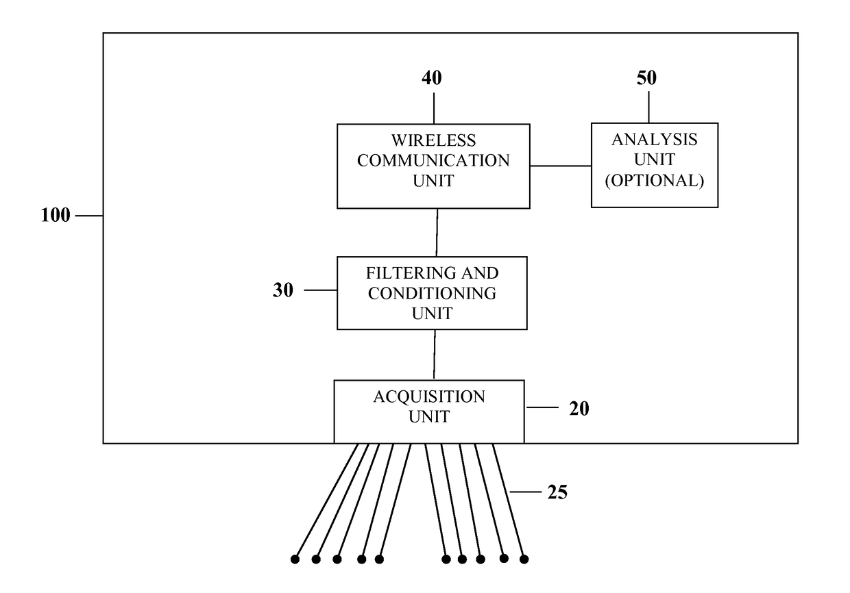
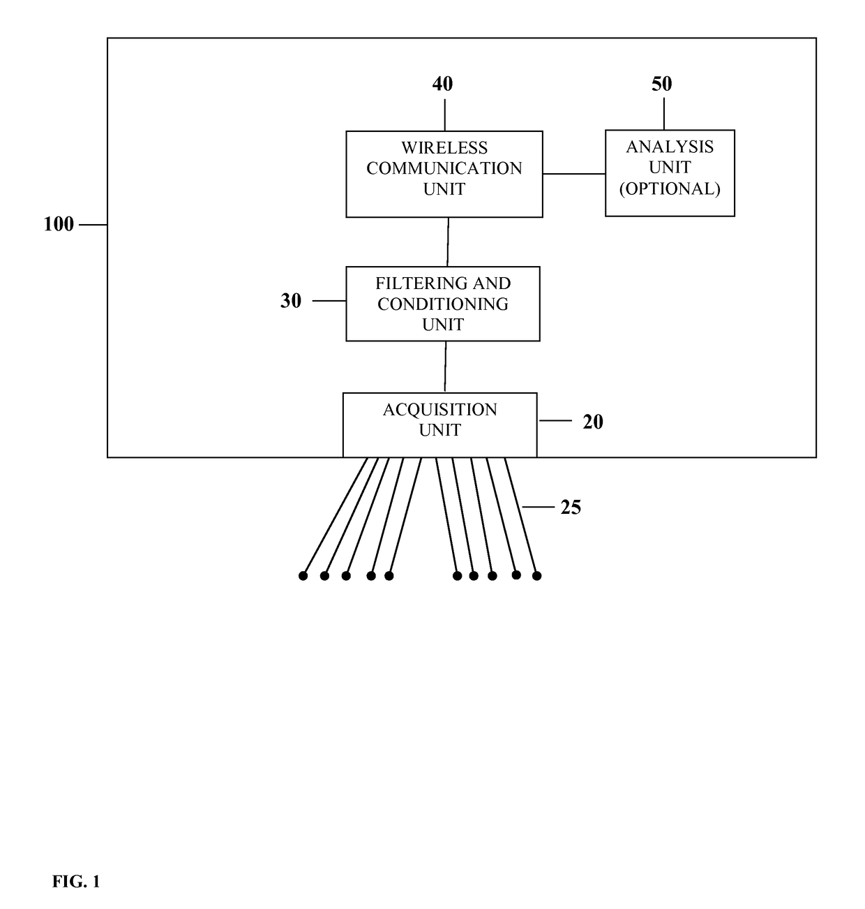
[0113]Interventional MRI allows physicians to perform minimally invasive and catheter-based diagnostic procedures, providing high-quality images of internal organs, without exposure to harmful ionizing radiation. I-MRI requires telemetry monitoring of patients' vital signs; however, existing telemetry monitors have electromagnetic compatibility (EMC) issues: MRI equipment is affected by electromagnetic interference (EMI) from telemetry systems, and telemetry data are degraded by the EMI generated by the MRI scanner. Commercial applications of the technology are expected to be in all areas of I-MRI. Because I-MRI enables physicians to perform minimally invasive procedures, eliminating the need for more invasive and traumatic procedures, its role in diagnostic evaluation is expected to grow rapidly.

[0114]As the field and applications of I-MRI continue to grow and diversify, the need for wireless-telemetry monitoring of various physiological sig...

example 2

MRI-Guided Cardiac Electrophysiology Study

[0120]This hypothetical example describes application of a medical device of this invention for the MR-guided cardiac electrophysiology imaging. The monitoring procedure is similar to that described in example 1. However, the system configuration required for this time-critical setting is different. First, the system uses two parallel data streams passed through both Filterbanks I and II, to allow clinicians monitor interchangeably or concurrently signals passed through both filterbanks Second, all data channels are transmitted at two different frequencies (2.4 and 5.2 GHz), using two wireless transmitters, to ensure uninterrupted transmission of all data channels in this time-critical setting. This redundant transmission ensures that the receiving station receives all the data channels if one transmission frequency becomes unavailable or experiences a transmission delay.

example 3

Magnetic-Resonance Imaging of the Brain

[0121]This hypothetical example describes application of a medical device of this invention for high-resolution brain imaging requires data recording from up to 100 channels simultaneously, at a high sampling frequency. The monitoring and setup procedures are similar to those described in examples 1 and 2. However, because the number of monitoring channels is bigger, the system configuration is expanded to include ten data acquisition modules with associated wireless transmitters, which are time-synchronized as described above.


PUM


Abstract

This multipurpose, modular system provides diagnostic-quality, wireless, multichannel monitoring in diverse settings, including interventional procedures guided by X-ray and MRI, with variable electromagnetic interference (EMI) and eliminates the need for multiple detachments / reattachments of patient cables when the patient is moved from one room / procedure to another. The system includes: 1) multiple filterbanks (filtering procedures) for recording both diagnostic-quality (broad-band) signals in the absence of EMI and narrow-band signals in the presence of EMI, with subsequent reconstruction of diagnostic-quality signals from the narrow-band signals; 2) filtering of EMI, using a priori and adaptive criteria about differences between the EMI and physiological signals' characteristics; 3) filtering of the magneto-hydrodynamic effect, using physiological measurements at different distances from the magnet (i.e., at different strengths of magnetic field) and changes in blood flow and blood pressure; and 4) multiple wireless transmitters for increasing reliability and speed (throughput) of the wireless data transmission.

Description

STATEMENT REGARDING FEDERALLY SPONSORED RESEARCH OR DEVELOPMENT[0001]This invention was made with government support under the contract HHSN268201200066C awarded by the National Institutes of Health. The government has certain rights in the invention.FIELD OF THE INVENTION[0002]This invention relates to the field of wireless biomedical devices and healthcare information management systems; and more specifically, to wireless monitoring of medical and health data (e.g., vital signs, electrocardiogram, blood pressure, pulse oximetry, electroencephalogram) in the setting of magnetic resonance imaging, X-ray guided cardiovascular procedures and other sources of electromagnetic interference.BACKGROUND OF THE INVENTION[0003]The following acronyms are used in this specification:[0004]ECG—electrocardiogramSSFP—steady state free-precessionEEG—electroencephalogramMHE—magneto-hydrodynamic effectEEG—electromyogramSVD—singular value decompositionMR—magnetic resonanceGMF—gradient magnetic fieldABP...

Claims


Application Information

Patent Timeline
Patent Type & Authority Patents(United States)
IPC IPC(8): A61B5/055A61B5/0402A61B5/00A61B5/0205A61B5/026A61B5/0476A61B5/0488A61B5/1455A61B5/021
CPCA61B5/0205A61B5/002A61B5/0402A61B5/055A61B5/7203A61B5/021A61B5/0263A61B5/0476A61B5/0488A61B5/14551A61B5/7225A61B5/318A61B5/369A61B5/389
Inventor SHUSTERMAN, VLADIMIR
Owner SHUSTERMAN VLADIMIR
Why Eureka
Try Eureka