System for pelletizing solid refuse fuel

a solid waste and pelletizing technology, applied in the direction of biofuels, waste based fuels, fuels, etc., can solve the problems of soil contamination, plastic waste degrading or decaying for a very long time, water pollution, etc., to prevent water pollution, reduce water treatment costs, and prevent air pollution.

Active Publication Date: 2017-05-30
PARK SUOOK YOUNG
View PDF7 Cites 0 Cited by
  • Summary
  • Abstract
  • Description
  • Claims
  • Application Information

AI Technical Summary

Benefits of technology

[0016]As described above, the system for pelletizing SRF according to the present invention has advantage of recycling plastic waste without using water, thereby preventing water pollution, reducing water treatment cost, treating a larger amount plastic waste compared to a wet process in which water is used, preventing air pollution attributable to incineration or landfill disposal of plastic waste, and reducing operation cost.
[0017]In addition, the system has another advantage of having a simple structure. Furthermore, the filter unit can be reused after dregs in the filter unit are removed because the filter is removable from the system. For this reason, the system has improved durability and incurs low cost.

Problems solved by technology

In the case of incineration, toxic fumes and incinerator ash containing hazardous heavy metals are generated, causing air pollution.
On the other hand, in the case of disposal in landfills, it takes a very long time for the plastic waste to degrade or decay, also causing soil contamination.
Accordingly, although it is possible to almost perfectly remove impurities from the plastic waste, it is difficult to completely remove water from the plastic waste through the dehydration process.
For this reason, the pellets are likely to contain moisture, resulting in degradation in quality of recycled products.
However, this process increases recycling cost, resulting in a decline in competitiveness of the recycled products.
However, since the device uses a cleaning process using water, a dehydration effect cannot be sufficiently obtained.

Method used


Image

  • System for pelletizing solid refuse fuel
  • System for pelletizing solid refuse fuel
  • System for pelletizing solid refuse fuel

Examples


Embodiment Construction

[0023]A system for pelletizing Solid Refuse Fuel (SRF) according to the present invention will be described in detail below with reference to the accompanying drawings. Any specific description about functions or constructions that are well known in related arts will be omitted, when such a description is likely to obscure the gist of the present invention. The terms described below should be interpreted in consistent of their functions in the present invention. Terms are usually differently defined according to intension of a client, operator, or user or to custom. Therefore, the terms below should be interpreted as having meanings that are consistent with their meanings in the context of the relevant art and the present disclosure, and will not be interpreted in an idealized or overly formal sense unless expressly so defined herein.

[0024]Throughout the drawings, the same reference numerals will refer to the same or like parts.

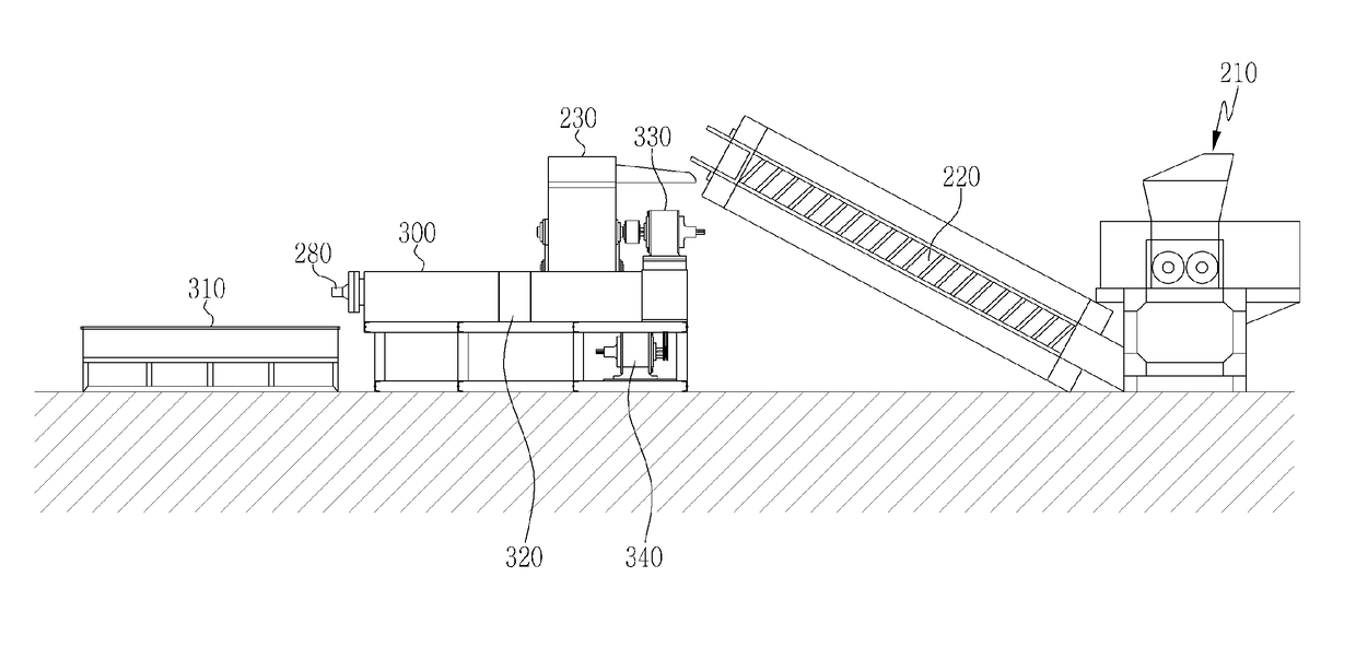
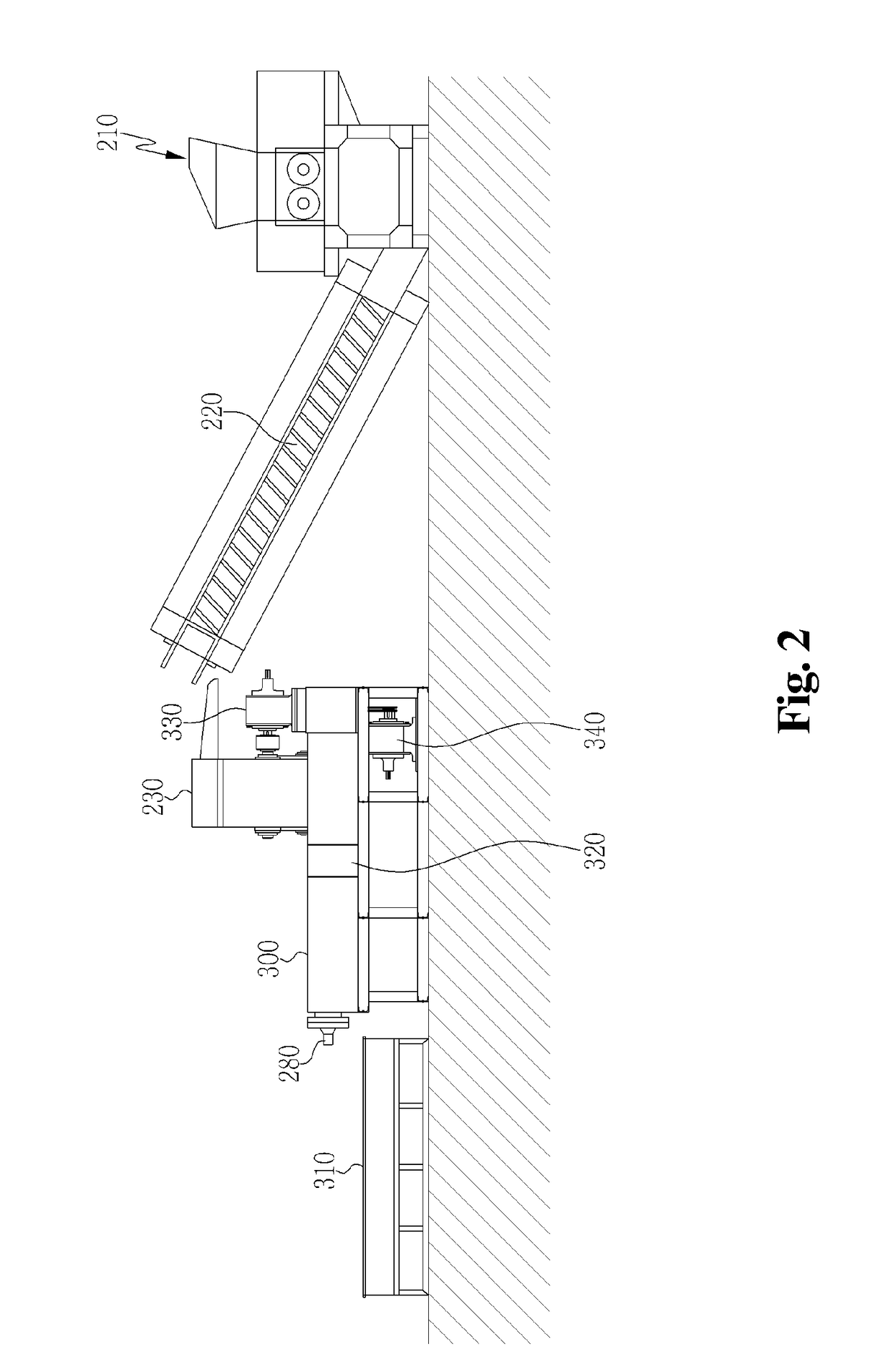
[0025]FIG. 2 is a schematic view illustrating a system ...


PUM

PropertyMeasurementUnit
metallicaaaaaaaaaa
internal diameteraaaaaaaaaa
heataaaaaaaaaa

Abstract

Disclosed is a system for pelletizing Solid Refuse Fuel (SRF). The system includes: a first crusher that primarily crushes plastic waste; a vibration sieve plate-conveyer that transports plastic waste that is primarily crushed by the first crusher; a second crusher that secondarily crushes the primarily crushed plastic waste sieved by the vibration sieve plate-conveyer; a first rotational shaft equipped with a first screw that fuses and transports the plastic waste which is secondarily crushed by the second crusher; a filter unit that is combined with the first rotational shaft and which removes impurities by filtering the secondarily crushed plastic waste that is fused and transported by the first screw; a second rotational shaft equipped with a second screw that transports impurity-free plastic waste filtered by the filter unit; and a molding machine that molds the plastic waste transported by the second screw.

Description

CROSS REFERENCE TO RELATED APPLICATION(S)[0001]This application claims the benefit of Korean Patent Application No. 10-2014-0024587, filed on Feb. 28, 2014, which is hereby incorporated by reference in its entirety into this application.BACKGROUND OF THE INVENTION[0002]Field of the Invention[0003]The present invention relates to a system for pelletizing Solid Refuse Fuel (SRF) to recycle plastic waste that occurs after plastic is used for agricultural, domestic, and industrial purposes. The present invention more particularly relates to a system for pelletizing SRF to recycle plastic waste instead of incinerating or disposing of plastic waste in landfills, without using cleaning water for cleaning the plastic waste, thereby preventing environmental pollution, more specifically water pollution.[0004]Description of the Related Art[0005]Generally, vinyl or plastic waste that occurs in a large amount in agricultural and fishing villages and industrial sites does not naturally degrade. A...

Claims


Application Information

Patent Timeline
Patent Type & Authority Patents(United States)
IPC IPC(8): B29C47/10B29C47/50B29C47/68B29C47/58B29B13/10B29B17/04B29B17/02B29B17/00B29C48/38B29C48/50B29C48/693B29K101/12B29K105/26
CPCB29B13/10B29B17/0412B29C47/1027B29C47/50B29C47/585B29C47/686B29B17/0042B29B2017/0089B29B2017/0224B29B2017/0468B29K2101/12B29K2105/26Y02E50/30Y02W30/62Y02E50/10B29C48/38B29C48/288B29C48/501B29C48/693C10L5/406C10L2290/56
Inventor PARK, SUOOK YOUNG
Owner PARK SUOOK YOUNG
Why Eureka
Try Eureka