Composite electrodes for the electrolysis of water

a technology of electrolysis and composite electrodes, applied in the direction of electrode coatings, energy input, multiple component coatings, etc., can solve the problems of large co2 emission, large tonnage of oxygen required by other methods, and large tonnage of oxygen, etc., to achieve the effect of improving the performance of the electrode according to the invention, enhancing the associated performance, and maximizing the surface area

Active Publication Date: 2018-06-05
CENT NAT DE LA RECHERCHE SCI +2
View PDF15 Cites 0 Cited by
  • Summary
  • Abstract
  • Description
  • Claims
  • Application Information

AI Technical Summary

Benefits of technology

[0052]The advantage of the mixture according to the invention is that it can be deposited on the solid or openwork collector, by usual deposition techniques which are readily available and make deposition possible in the form of layers of variable thicknesses ideally of the order of 10 to 100 μm.
[0053]According to the invention, the mixture can be prepared by any technique known to a person skilled in the art, in particular by mixing the binder and the at least one electrocatalytic material in the form of divided powder in a suitable solvent or mixture of suitable solvents in order to obtain a mixture with the rheological properties that make it possible to deposit the composite electrode materials in the form of a film with a controlled thickness on an electronic-conductor substrate. The use of the electrocatalytic material in the form of divided powder makes it possible to maximize the surface area developed by the electrodes and to enhance the associated performance. A person skilled in the art will know how to choose the different formulation parameters in the light of his general knowledge and the physicochemical characteristics of said mixtures.
[0054]The performance of the electrode according to the invention is improved compared with the conventional devices as, contrary to the electrodes of the prior art, any electrocatalytic material in the form of a powder with a large specific surface area is capable of being deposited in the form of a layer of variable thickness, which will be determined by a person skilled in the art as a function of the results that he wishes to obtain.

Problems solved by technology

Other methods also require large tonnages of oxygen, in particular the bleaching of papermaking pulp, the reprocessing of certain types of chemical waste and the production of high-temperature flames.
These two methods have the drawback of emitting large quantities of CO2.
However, the cost of the polymer membrane and the use of catalysts based on noble metals lead to relatively expensive equipment.or an O2− ion-conducting ceramic membrane: one of the features of this technology (SOFC—Solid Oxide Fuel Cell) is the use of a solid electrolyte, which acts as a conductor for the oxygen anion.
However, managing concentrated acid electrolytes poses corrosion problems, and the technical solutions are very expensive.
The drawbacks of this technique are the limitation of the surface area developed by the electrode in contact with the electrolyte, leading to a deficiency in the associated performance and the complexity of the chemical compositions.
The two main drawbacks of this method are its complexity and the choice of the materials used, which are not entirely suitable for this type of application.
In fact, the polymer binder used (PTFE) is insulating and hydrophobic, which tends to reduce the performance of the electrodes.
In the different types of electrochemical reactions involved in the electrolysis of water in an alkaline medium, the use thereof is nevertheless difficult.
This difficulty is, among other things, linked to the production of gas occurring at the two electrodes, which gives rise to stresses that are disadvantageous to the stability and mechanical integrity of the electrodes and which, as a result, leads to a loss of activity of the electrodes over time due to the loss of catalytic material.

Method used


Image

  • Composite electrodes for the electrolysis of water
  • Composite electrodes for the electrolysis of water
  • Composite electrodes for the electrolysis of water

Examples


example 1

on of the Electrodes

1.1. Material

[0099]The electrodes are manufactured on the basis of commercial micrometric Ni powders (5 μm, purity 99.7%, Aldrich), Co (>99.8%, Fluka), Co3O4 (>71% Co, Fluka) and laboratory-synthesized submicrometric and nanometric powders.

1.2. Preparation of the Support

[0100]A grid of 316L stainless steel (Gantois ref. no. 42.73 FR 0.25) is cut out and folded back on itself lengthwise, in order to obtain the final dimension of the electrode.

1.3. Preparation of the Electrode by Moulding the Film

[0101]1.3.1 Preparation of the Film

[0102]A mixture comprising 90% by mass of a catalytic powder and 10% by mass of polymer binder (PBI) is dissolved at a rate of 5% by mass in dimethyl sulphoxide (DMSO).

[0103]A mould is produced using a self-adhesive Teflon® film deposited on a previously cleaned glass plate. A volume of the catalytic powder—PBI mixture is deposited in the mould. The volume of deposited mixture is suitable for the final quantity of catalytic powder desired...

example 2

ization of the Electrodes Based on Micrometric Nickel Powders and PBI

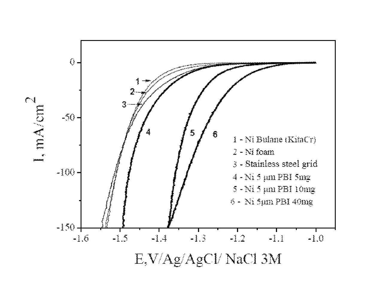
[0107]The catalytic activities of the electrodes according to the invention are determined from the polarization curves. The measurements were carried out in a standard cell with three electrodes (Ag / AgCl / 3MNaCl reference electrode, platinum counter electrode, and work electrode corresponding to the electrode to be characterized). The set of characterizations was carried out at ambient temperature in a 1 mol / L solution of potassium hydroxide.

[0108]A commercial nickel powder having an average particle diameter of 5 μm and PBI is used. The composite electrodes based on nickel powder are prepared by moulding and have a Ni powder loading rate of 5, 10 and 40 mg / cm2 of electrode.

[0109]The polarization curves obtained are shown in FIG. 1. They were recorded at a speed of linear potential variation of 1 mV / s. The curves shown were corrected for ohmic drop. These different electrodes were compared with a stainless steel el...

example 3

s Based on Nanometric Nickel Particles and PBI

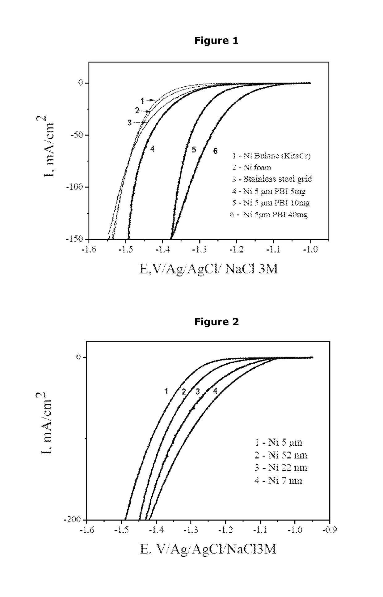
[0112]Composite electrodes were manufactured with laboratory-synthesized nickel powders of nanometric size and PBI in accordance with Example 1. The Ni loading rate of the electrodes is 5 mg / cm2.

[0113]The polarization curves for the different types of electrodes are given in FIG. 2.

[0114]With a nanometric structuring of the nickel and keeping the production process of the electrodes identical to that used for the micrometric powders, better results than those obtained for the micrometric powders can be observed for certain compositions. Here, at 100 mA / cm2 of electrode, lower overpotentials are recorded, for example equal to −352 mV for an electrode based on nanostructured nickel powder with an average particle size of 52 nm, equal to −321 mV for an electrode based on nanostructured nickel powder with an average particle size of 22 nm, equal to 286 mV for an electrode based on nanostructured nickel powder with an average particle size of...


PUM

PropertyMeasurementUnit
diameteraaaaaaaaaa
diameteraaaaaaaaaa
diameteraaaaaaaaaa

Abstract

An electrode is provided that is suitable for use with the electrolysis of water in a liquid electrolyte medium, the electrode formulated by the following formulation method:
    • a) dissolving, in a volatile solvent or a mixture of volatile solvents, at least one ion-conducting polymer binder that allows, in the solid state, the diffusion of the gases formed during electrolysis;
    • b) adding, to the solution obtained in step a), at least one electrocatalytic material in the form of divided powder, in order to obtain a mixture; and
    • c) depositing the mixture obtained in step b) on a metallic or metallic-type conductive support or collector, said support or said collector being openwork and chemically stable in an aqueous medium,
steps a) and b) being able to be implemented simultaneously, successively or to be reversed.

Description

BACKGROUND[0001]A subject of the present invention is an electrode suitable to be used for the electrolysis of water in a liquid electrolyte medium, a method for formulating such an electrode, a device for the electrolysis of water comprising said electrode, and a method for producing a hydrogen / oxygen mixture or hydrogen alone or oxygen alone.[0002]Pure oxygen is mainly used in the iron and steel industry and in petrochemistry. Other methods also require large tonnages of oxygen, in particular the bleaching of papermaking pulp, the reprocessing of certain types of chemical waste and the production of high-temperature flames. Oxygen is also used as a medical gas in normobaric or hyperbaric oxygen therapy.[0003]Currently, oxygen is obtained industrially mainly by cryogenic separation of the compounds of air, i.e. by liquefaction of air followed by fractional distillation. Pure oxygen can also be obtained by the electrolysis of water.[0004]Hydrogen is one of the raw materials of the c...

Claims


Application Information

Patent Timeline
Patent Type & Authority Patents(United States)
IPC IPC(8): C25B11/03C25B11/04C25B1/04
CPCC25B11/04C25B1/04C25B11/03C25B11/0489Y02P20/133Y02E60/366Y02P20/132C25B11/095Y02E60/36Y02P20/129
Inventor PATRU, ALEXANDRAFAVIER, FREDERICJEREZ, NICOLAS
Owner CENT NAT DE LA RECHERCHE SCI
Why Eureka
Try Eureka