
Nanostructures and applications thereof

a nanostructure and nanotechnology, applied in the direction of radioactive preparation forms, drug compositions, pharmaceutical delivery mechanisms, etc., can solve the problems of high radiation doses, damage to surrounding healthy tissue, damage to normal tissue in the path of beams, etc., to reduce radiation dose, monitor the response, and increase the effective dose

Active Publication Date: 2018-06-19
SPAGO NANOMEDICAL
View PDF17 Cites 0 Cited by
  • Summary
  • Abstract
  • Description
  • Claims
  • Application Information

AI Technical Summary

Benefits of technology

[0020]Some advantages with the nanostructures disclosed herein over prior art include a “theranostic” application in which the nanostructure can be used to diagnose cancer, deliver tumor-targeted therapy as well as monitor the response to therapy. A passive targeted approach as utilized by the current invention, enables for treatment and detection of larger tumor masses as well as smaller tumor loads and metastasized disease. The disclosed nanostructure enables for a higher effective dose to be delivered to the tumor and thus lowers the radiation dose as well as limits the general toxicity and damage to surrounding tissue as frequently seen with systemic chemotherapy and external beam radiotherapy. The design of the current invention allows for simplified management and handling at the hospital and thus improves utility in clinical practice.

Problems solved by technology

Although the intensity, location and timing for external radiation can be well controlled and modulated, disadvantages associated with this technique include the destruction of normal tissue in the path of the beam as well as damage to tissues surrounding the tumor.
The risk of damaging surrounding healthy tissue speaks against external radiotherapy to deeply situated tumors and tumors situated next to vital organs.
Furthermore, high radiation doses are frequently required to penetrate the tissue.
However, despite a large number of publications covering nanosized carriers for cancer therapeutics, relatively few have reached clinical trials, and only a handful are approved by the FDA (Taurin et al., J. Controlled release 2012, 164).
Actively targeted approaches are often limited by insufficient delivery of therapeutic agents to tumor sites due to relatively low and heterogeneous expression of tumor specific targets.
Moreover, expression of target proteins on non-tumorigenic cells could lead to systemic toxicity.
Many of the approaches to radiotherapy involving nanocarriers suggested in the literature, e.g. nanocarriers based on liposomes (Malam et al., Trends Pharmacol Sci. 2009, 30:11) suffer from the drawback that the radioactive isotope has to be incorporated in or encapsulated by or covalently bound to the nanocarrier by one or more chemical steps.
This is usually not desirable since normally the radioisotope would be supplied by a third party and incorporated in the nanocarrier at a hospital with limited laboratory facilities.
Also, many of the approaches to radioisotope therapy involving alleged nanocarriers mentioned in the literature suffer from the drawback that the nanocarrier is not really a nanocarrier as it is larger than 100 nm and due to its large size suffers from the drawback of not delivering the radioisotope to the tumor tissue in an effective way.
In addition, solid tumors tend to lack functional lymphatics.
Combined, these features limit the removal of extravasated nanomaterials from most solid tumors.

Method used


Image

  • Nanostructures and applications thereof
  • Nanostructures and applications thereof
  • Nanostructures and applications thereof

Examples


example 1a

Polymerization of 1,1-Bis(Triethoxysilylpropyl)-1,1-Bis(Dimethylphosphonato)Methane (Cpd 1) to Yield Central Parts Xa

[0340]Cpd 1 (640.8 mg, 1 mmol, synthesized as described in Example 1, EP2572736 A1) was dissolved in 20 ml aqueous 80% ethylene glycol in a three neck round bottom flask. The reaction mixture was degassed by applying vacuum to the reaction flask and thereafter filling with nitrogen gas. This procedure was repeated three times. Thereafter the reaction mixture was stirred for 24 h at 114° C. After allowing the clear solution to cool to room temperature it was filtered through a 0.45 μm sterile filter (Pall Corporation).

example 1a1

on Time: 14.16 Min

[0341]0.5 mg / ml albumin (from chicken egg white) solution resulted in a size: DLS=7.0 nm & GPC peak retention time=12.52 min.[0342]GPC retention time—Superose 12 10 / 300 GL, 100 mM NH4CO3, pH=7.4, flow 1 ml / min.

example 1b

erization of Cpd 1 to Yield Central Parts Xb

[0343]20 ml of central parts Xa were mixed with 32 ml MilliQ water in a three neck round bottom flask. The reaction mixture was degassed by applying vacuum to the reaction flask and thereafter filling with nitrogen gas. This procedure was repeated three times. Thereafter the reaction mixture was stirred for 24 h at 114° C. Cpd 1 (5.126 g, 8 mol) was dissolved in 128 ml ethylene glycol and injected into the reaction flask using a syringe pump to a final concentration of 100 mM phosphorus. The pump injection settings were 200 μl / min, selected syringe size 50 and the injection syringe used was 50 ml. A timer was connected to the pump, so that it only injected the solution 15 min per hour. The reaction mixture was stirred and heated for 49 h at a set temperature of 122° C. The actual temperature in the reaction flask was 100° C. (when 0 ml of cpd 1 solution was added), 103° C. (after 50 ml of cpd 1 solution was added), 106° C. (after 100 ml of...


PUM

PropertyMeasurementUnit
diameteraaaaaaaaaa
hydrodynamic diameteraaaaaaaaaa
molecular weightaaaaaaaaaa

Abstract

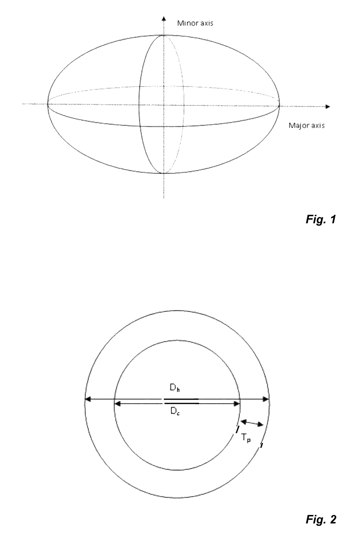
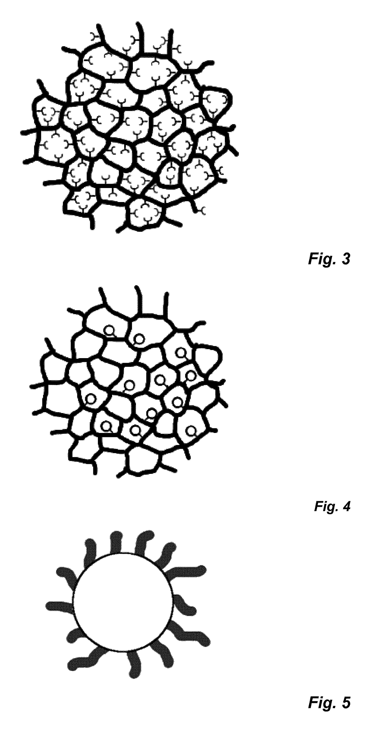
Disclosed herein are globular nanostructures having a hydrodynamic diameter (Dh) of 8-100 nm comprising a central part and a peripheral part, wherein said central part has a calculated diameter (Dc) of 6-90 nm and said peripheral part has an estimated thickness (Tp) so that Dh=Dc+2Tp, wherein said central part comprises: (i) a crosslinked polymeric framework comprising monomer residues wherein at least 30% by number of the monomer residues have crosslinked thereby forming the crosslinked polymeric framework and / or (ii) a branched polymeric framework comprising monomer residues wherein the number of branch points is at least 30% of the number of monomer residues, wherein said central part comprises chelating groups of which at least 4 allow chelation of at least one multiply charged cation, wherein said chelating groups are independently selected from the group consisting of —COOR1, —P═O(OR1)(OR2), and —S(═O)2OR1, wherein R1 and R2 are independently selected from the group consisting of a negative charge, H, and lower alkyls, and wherein said peripheral part comprises a synthetic polymer material covalently attached to the central part, wherein the synthetic polymer material is hydrophilic and bioinert, and electrically neutral or zwitterionic. Also disclosed are compositions comprising such nanoparticles, and optionally also a radionuclide, use of such compositions, kits containing such compositions and methods for obtaining such compositions.

Description

PRIORITY STATEMENT[0001]This patent application is a U.S. national stage filing under 35 U.S.C. § 371 of International Application No. PCT / EP2015 / 056739 filed on 27 Mar. 2015, which claims priority to European Patent Application No. 14162399.1 filed on 28 Mar. 2014. The entire disclosures of each of the above recited applications are incorporated herein by reference.TECHNICAL FIELD OF THE INVENTION[0002]The present invention relates to bioinert chelating polymeric nanostructures with applications in systemic radiotherapy and cancer imaging.BACKGROUND[0003]The gold standard for cancer treatment is surgery. In cases where surgery alone is not curative, multimodality regimens including chemotherapy and radiation treatment are used. About half of all cancer patients today are treated with radiotherapy, either alone or in combination with other treatments. Radiation delivered as external beams offers a relatively simple and practical approach to causing radiation damage to the tumor. Alt...

Claims


Application Information

Patent Timeline
Patent Type & Authority Patents(United States)
IPC IPC(8): C08G77/30A61K51/06A61K51/12
CPCA61K51/065C08G77/30A61K51/1251A61P35/00A61K49/1818A61K51/12
Inventor AXELSSON, OSKARBACKSTROM, SANIAPETORAL, JR., RODRIGO
Owner SPAGO NANOMEDICAL
Learn More