Electronic caliper using a reduced offset induced current position transducer

a transducer and offset technology, applied in the field of electronic calipers, can solve the problems of inability to eliminate the source of error, inability to reduce the accuracy of the transducer, so as to improve the proportion of the useful output signal component, improve the winding configuration, and improve the fabrication accuracy

Inactive Publication Date: 2002-01-01
MITUTOYO CORP
View PDF17 Cites 36 Cited by
  • Summary
  • Abstract
  • Description
  • Claims
  • Application Information

AI Technical Summary

Benefits of technology

This invention provides an electronic caliper using an induced current position transducer with improved winding configurations. The improved winding configurations increase the proportion of the useful output signal component relative to extraneous ...

Problems solved by technology

This offset V.sub.o is an extraneous signal component that complicates signal processing and leads to undesirable position measurement errors.
Experience in manufacturing a transducer indicates it is practically impossible to eliminate this source of error from the induced current position transducer of a conventional caliper.
Such extraneous signals complicate the required signal processing circuitry and otherwise lead to errors which compromise the accuracy of the transducer.
However, the effectiveness of this technique alone depends on the degree of separation between the transmitter and receiver windings.
Hence, this technique contradicts the need for hi...

Method used


Image

  • Electronic caliper using a reduced offset induced current position transducer
  • Electronic caliper using a reduced offset induced current position transducer
  • Electronic caliper using a reduced offset induced current position transducer

Examples


first embodiment

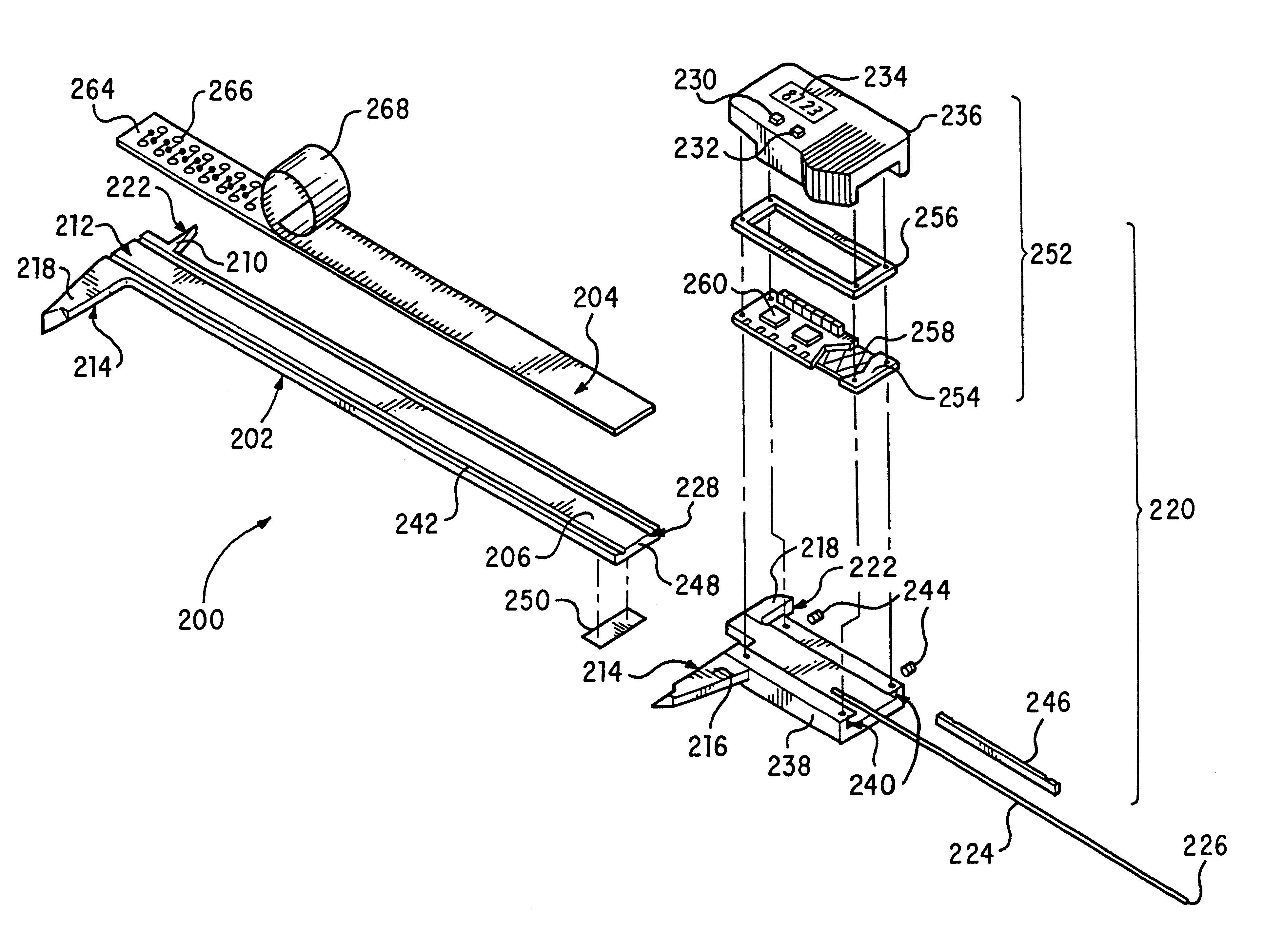
FIGS. 6 and 7 show the reduced-offset incremental induced current position transducer 200 used in the electronic caliper of this invention, which produces an output type usually referred to as "incremental". "Incremental" output is defined as a cyclic output which is repeated according to a design-related increment of transducer displacement.

In particular, FIG. 6 shows a first embodiment of the reduced offset scale 204 of the transducer 200. The reduced-offset scale 204 includes a first plurality of coupling loops 274 interleaved with a second plurality of coupling loops 276. Each of the coupling loops 274 and 276 is electrically isolated from the others of the first and second plurality of coupling loops 274 and 276.

Each of the first plurality of coupling loops 274 includes a first loop portion 278 and a second loop portion 280 connected by a pair of connecting conductors 282. Similarly, each of the second plurality of coupling loops 276 includes a first loop portion 284 and a seco...

second embodiment

FIG. 8 shows a read head that can be used with a scale according to FIG. 6. The receiver in this version of the read head has three receiver windings 318, 320 and 322. The receiver windings are offset from each other along the measurement axis by 1 / 3 of the wavelength .lambda.. FIG. 9 shows the signal functions from the three receivers as a function of the position along the measurement axis.

It should be appreciated that perfectly sinusoidal output functions are difficult to achieve in practice, and that deviations from a perfect sinusoidal output contain spatial harmonics of the fundamental wavelength of the transducer. Therefore, the three phase configuration of this second embodiment of the reduced-offset induced current position transducer has a significant advantage over the first embodiment of the reduced offset induced current position transducer, in that the third harmonic content in the separate receiver windings' signal can be largely eliminated as a source of position mea...

third embodiment

FIGS. 11A-11D show the read head and scale for the reduced offset induced current position transducer of the linear scale of this invention. This embodiment contains only one transmitter winding loop 490, which is placed on one side of the receiver windings 496 and 498 on the read head 458. The scale 404 is a two layer printed circuit board (PCB). Pattern forming coupling loops 474 and 476 are arrayed on the scale 404 along the measurement axis.

Each coupling loop 474 includes a first loop portion 478 which is connected by connection lines 482 to a second loop portion 480. The first and second loop portions 478 and 480 are connected so that an induced current produces the same polarity field in the first loop portion 478 and the second loop portion 480. Each coupling loop 476 includes a first loop portion 484 which is connected by connection lines 488 to a second loop portion 486. The first and second loop portions 484 and 486 are connected so that an induced current produces fields ...


PUM


Abstract

An electronic caliper having a reduced offset position transducer that uses two sets of coupling loops on a scale to inductively couple a transmitter winding on a read head on a slide to one or more receiver windings on the read head. The transmitter winding generates a primary magnetic field. The transmitter winding is inductively coupled to first loop portions of first and second sets of coupling loops by a magnetic field. Second loop portions of the first and second sets of coupling loops are interleaved and generate secondary magnetic fields. A receiver winding is formed in a periodic pattern of alternating polarity loops and is inductively coupled to the second loop portions of the first and second sets of coupling loops by the secondary magnetic fields. Depending on the relative position between the read head and the scale, each polarity loop of the receiver winding is inductively coupled to a second loop portion of either the first or second set of coupling loops. The relative positions of the first and second loop portions of the first and second sets of coupling loops are periodic and dependent on the relative position of the coupling loops on the scale.

Description

BACKGROUND OF THE INVENTION1. Field of InventionThis invention relates to an electronic caliper. More particularly this invention is directed to electronic calipers using a reduced offset induced current position transducer.2. Description of Related ArtU.S. patent application Ser. No. 08 / 645,483 filed May 13, 1996, and incorporated herein in its entirety, discloses an electronic caliper using an inductive position transducer.The operation of the electronic caliper using the inductive position transducer described in the application Ser. No. '483 is generally shown in FIGS. 1, 2, and 3. As shown in FIG. 1, an inductive caliper 100 includes an elongated beam 102. The elongated beam 102 is a rigid or semi-rigid bar having a generally rectangular cross section. A groove 106 is formed in an upper surface of the elongated beam 102. An elongated measuring scale 104 is rigidly bonded to the elongated beam 102 in the groove 106. The groove 106 is formed in the beam 102 at a depth about equal...

Claims


Application Information

Patent Timeline
IPC IPC(8): G01B3/20G01D5/12G01D5/20G01B7/00G01B7/02G01B21/02
CPCG01B3/205G01D5/2086
Inventor ANDERMO, NILS I.MASRELIEZ, KARL G.
Owner MITUTOYO CORP
Why Eureka
Try Eureka