Dual battery power system for an implantable cardioverter defibrillator with voltage booster

Inactive Publication Date: 2005-08-16
ANGEION
View PDF16 Cites 12 Cited by
  • Summary
  • Abstract
  • Description
  • Claims
  • Application Information

AI Technical Summary

Benefits of technology

[0014]The major advantage of the present invention is that each battery source voltage can be optimized for the particular circuit wherein it is used. The first battery source is preferably a relatively low current, low voltage source, from 1.5 to 3.0 V typically; whereas the second battery source is preferably comprised of as high of a current and voltage as battery chemistry and battery packaging efficiencies allow, typically ranging from 6 to 18 V.
[0015]Unlike existing implantable cardioverter defibrillators, a preferred embodiment of the present invention utilizes a separate hardware-based, low-power monitoring circuitry to monitor for certain wake-up conditions which will then activate the output delivery circuitry which includes a microprocessor that performs further detection and, if necessary, selects an appropriate cardioversion/defibrillation therapy to be delivered. The output delivery circuitry includes additional hardware circuitry that, when enabled, can deliverydeliver pacing therapy pulses with energy supplied from the output power source battery without the need to wake the microprocessor.
[0016]Because the two batteries of the present invention can be optimized for their particular functions, different assumptions about the total energy requirements of the implantable cardioverter defibrillator can be made. For example, all existing manufactured implantable cardioverter defibrillators provide power systems which are designed to supply an initial number of defibrillation countershocks of at least 250 shocks. In a single ba

Problems solved by technology

Some of these parameters have some measure of mutual exclusively, making it difficult to optimize the battery of electronics without making compromises to the design of the implantable device.
As the device ages, its ability to deliver an adequate number of defibrillating shocks declines as the battery is depleted by the monitoring electronics.
Similarly, if a patient receives a large number of shocks soon after implant, the remaining monitoring life is reduced.
Thus, it is difficult to assess the condition of the battery and its remaining useful life after it has been in use for a period of time.
A further disadvantage of the single battery configuration is that the ideal voltage requirements for the monitoring and output functions are opposite.
All existing manufactured implantable cardioverter defibrillators have comp

Method used


Image

  • Dual battery power system for an implantable cardioverter defibrillator with voltage booster
  • Dual battery power system for an implantable cardioverter defibrillator with voltage booster
  • Dual battery power system for an implantable cardioverter defibrillator with voltage booster

Examples


Example

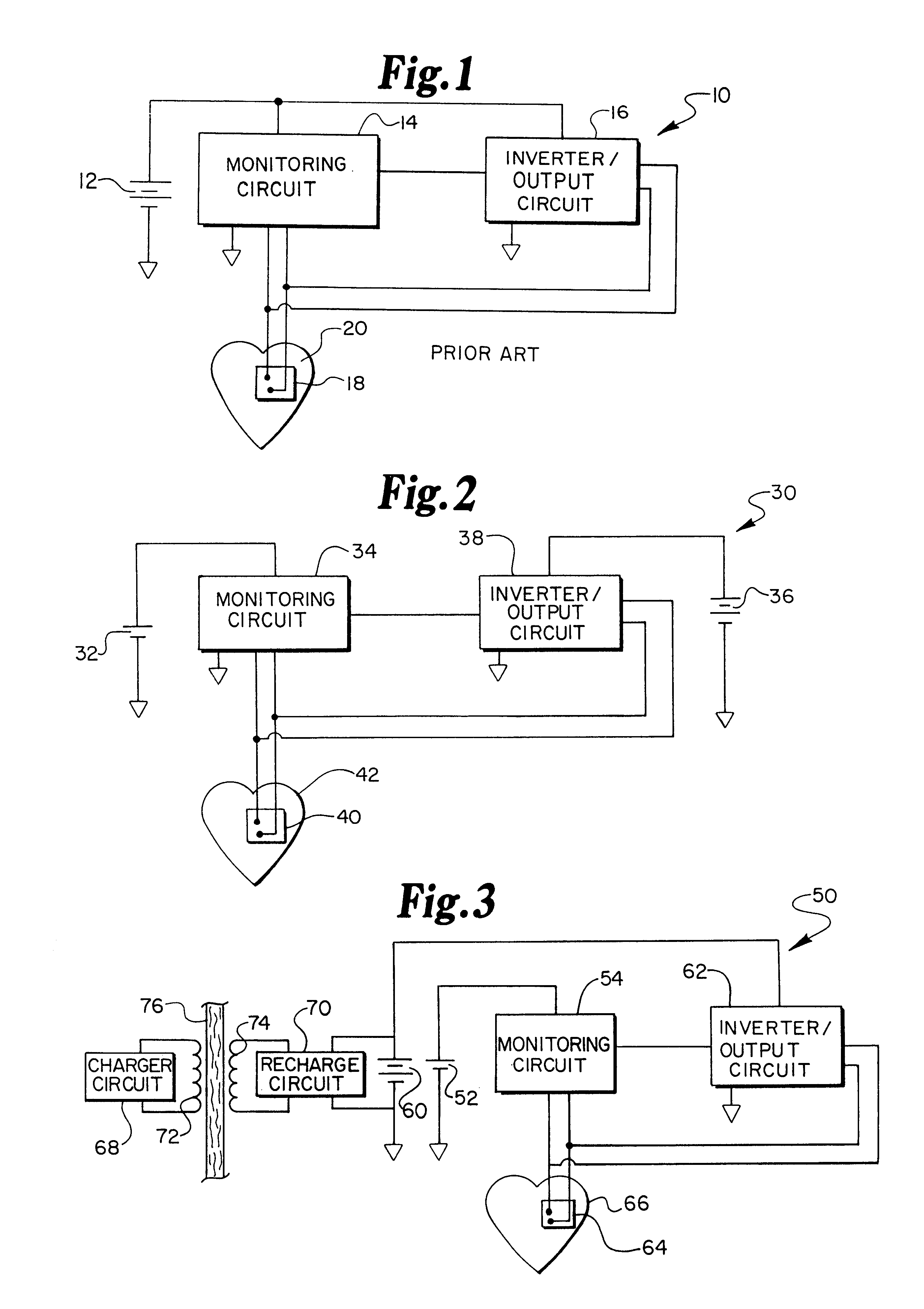
[0025]FIG. 1 illustrates a single battery system for an implantable defibrillator system 10 including a single battery 12, which provides power both to a monitoring circuit 14 and an inverter / output circuit 16 simultaneously. The monitoring circuit 14 and the inverter / output circuit 16 are interconnected to each other, and to two or more implanted electrodes 18 located on, near or in a heart 20. The implanted electrodes 18 include appropriate leads and sensors to monitor the electrical activity of the heart 20 and to deliver an appropriate electrical therapy to the heart 20 in the event that the monitoring circuit detects a cardiac arrhythmia. As discussed in the background of the invention, the electrical capacity of the single battery 12 may be excessive in relation to the circuit requirements of the monitoring circuit 14, and marginal or even somewhat lacking in electrical size in relation to the circuit requirements of the inverter / output circuit 16.

[0026]FIG. 2 illustrates a bl...


PUM


Abstract

An improved dual battery power system uses two separate battery power sources for an implantable cardioverter defibrillator, each having optimized characteristics for monitoring functions and for output energy delivery functions, respectively. The monitoring functions are supplied electrical power by a first battery source, such as a conventional pacemaker power source in the form of a lithium iodide battery which is optimized for long life at very low current levels. The output energy delivery functions are supplied by a separate second battery source, such as a pair of lithium vanadium pentoxide batteries, which is optimized for high current drain capability and low self-discharge for long shelf life. The first battery source provides electrical power only to the monitoring functions of the implantable cardioverter defibrillator, and the second battery source provides all of the electrical power for the output energy delivery functions.

Description

RELATED APPLICATIONS[0001]This application is a continuation-in-part application of an application filed in the United States Patent and Trademark Office on Jul. 16, 1992, entitled DUAL BATTERY SYSTEM FOR IMPLANTABLE DEFIBRILLATOR, Ser. No. 07 / 913,626, now U.S. Pat. No. 5,235,979 which is a file-wrapper continuation of an application by the same title filed on Mar. 3, 1991, both of which are assigned to the assignee of the present invention, and the disclosure of which is incorporated by reference in the present application. This application is related to a co-pending application filed in the United States Patent and Trademark Office on Mar. 15, 1993, entitled IMPLANTABLE CARDIOVERTER DEFIBRILLATOR HAVING A SMALLER DISPLACEMENT VOLUME, Ser. No. 08 / 033,632,<?delete-end id="DEL-S-00002" ?> <?insert-start id="INS-S-00001" date="20050816" ?>U.S. Pat. No. 5,405,363, which issued on Apr. 11, 1995, and which is assigned to the assignee of the present invention and the disclosu...

Claims


Application Information

Patent Timeline
IPC IPC(8): A61N1/39A61N1/378H01M2/10H01M6/50H01M16/00
CPCA61N1/3787A61N1/3931A61N1/3956A61N1/3975H01M6/5016H01M16/00
Inventor ADAMS, THEODORE P.BRUMWELL, DENNIS A.PERTTU, JOSEPH S.SUPINO, CHARLES G.
Owner ANGEION
Why Eureka
Try Eureka