
Signal processing utilizing a tree-structured array

a tree structure and signal processing technology, applied in the field of data transmission systems, can solve the problems of difficult transmission of such audio tracks over limited bandwidth transmission systems, inability to use sub-bands that correspond to these radio signals, and high storage requirements for even a short recording, so as to achieve the effect of reducing the computational workload

Inactive Publication Date: 2008-04-29
HYBRID AUDIO
View PDF21 Cites 30 Cited by
  • Summary
  • Abstract
  • Description
  • Claims
  • Application Information

AI Technical Summary

Benefits of technology

[0028]A decompression system according to the present invention regenerates a time-domain audio signal from the sets of frequency components such as those generated by a compression system according to the present invention. The decompression system receives a compressed audio signal comprising sets of frequency components, the number of frequency components in each set being M. The decompression apparatus synthesizes M time domain audio signal values from each of the received set of frequency components. The synthesis sub-system generates 2M polyphase components from the set of frequency components. Then it generates a W entry array from the polyphase phase components and multiples each entry in the array by a corresponding weight value derived from a prototype filter. The time domain audio samples are then generated from the weighted array. The generated samples are stored in a FIFO buffer and outputted to a D / A converter. The FIFO buffer generates a signal indicative of the number of time domain audio signal values stored therein. The rate at which these sample values are outputted to the D / A converters is determined by clock. The preferred embodiment of the decompression system includes a controller that uses the level indicator in the FIFO buffer or other operating system loading parameter to adjust the computational complexity of the algorithm used to synthesize the time domain samples. When the level indicator indicates that the number of time domain samples stored in the FIFO buffer is less than a first predetermined value, the normal synthesis operation is replaced by one that generates an approximation to the time domain samples. This approximation requires a smaller number of computations than would be required to generate the time domain audio signal values. The approximation may be generated by substituting a truncated or shorter prototype filter or by eliminating the contributions of selected frequency components from the computation of the polyphase components. In stereophonic systems, the controller may also switch the synthesis system to a monaural mode based on average frequency components which are obtained by averaging corresponding frequency components for the left and right channels.

Problems solved by technology

Because of the imperfect shielding of the wires, interference from strong radio stations will be picked up by the twisted pair.
Hence, the sub-bands that correspond to these radio signals are not usable.
The total storage needed for even a short recording is too high for many computer applications.
In addition, the digital bit rates inherent in non-compressed high fidelity audio recordings makes the transmission of such audio tracks over limited bandwidth transmission systems difficult.
Unfortunately, the replacement of the frequency components generated by the analysis filter band with a quantized approximation thereto results in artifacts that do depend on the detail characteristics of the filter banks.
When the frequency components are replaced by approximations, an error is introduced in each component.
However, if the segment is too short, there is insufficient spectral resolution to acquire information needed to properly determine the minimum number of bits needed to represent each frequency component.
On the other hand, if the segment is too long, temporal resolution of the human auditory system will detect artifacts.
Systems which utilize uniform frequency bands are poorly suited for systems designed to take advantage of this type of approximation.
This leads to temporal artifacts that become audible at higher frequencies.
Hence, systems in which the audio segment is decomposed into uniform sub-bands with adequate low-frequency resolution cannot take full advantage of the critical band properties of the auditory system.
While tree structured filter banks having many layers may be used to decompose the frequency spectrum into critical bands, such filter banks introduce significant aliasing artifacts that limit their utility.
Unfortunately, filter banks based on QMF filters which divide the signal into two bandlimited signals require large numbers of levels.
Prior art audio compression systems are also poorly suited to applications in which the playback of the material is to be carried out on a digital computer.
Computer based audio and video systems have been limited to the use of costly outboard equipment such as an analog laser disc player for playback of audio and video.
This has limited the usefulness and applicability of such systems.
With such systems it is necessary to provide a user with a highly specialized playback configuration, and there is no possibility of distributing the media electronically.
Until recently, the use of high quality audio on computer platforms has been limited due to the enormous data rate required tier storage and playback.
Quality has been compromised in order to store the audio data conveniently on disk.
Although some increase in performance and some reduction in bandwidth has been gained using conventional audio compression methods, these improvements have not been sufficient to allow playback of high fidelity recordings on the commonly used computer platforms without the addition of expensive special purpose hardware.
Unfortunately, this solution requires that the audio material be coded at various quality levels.
The cost and complexity of maintaining such multi-format libraries makes this solution unattractive.
In addition, the storage requirements of the multiple formats partially defeats the basic goal of reducing the amount of storage needed to store the audio material.
This assumption is not always true in practice.
This problem has not been adequately solved in prior art systems.

Method used


Image

  • Signal processing utilizing a tree-structured array
  • Signal processing utilizing a tree-structured array
  • Signal processing utilizing a tree-structured array

Examples


Embodiment Construction

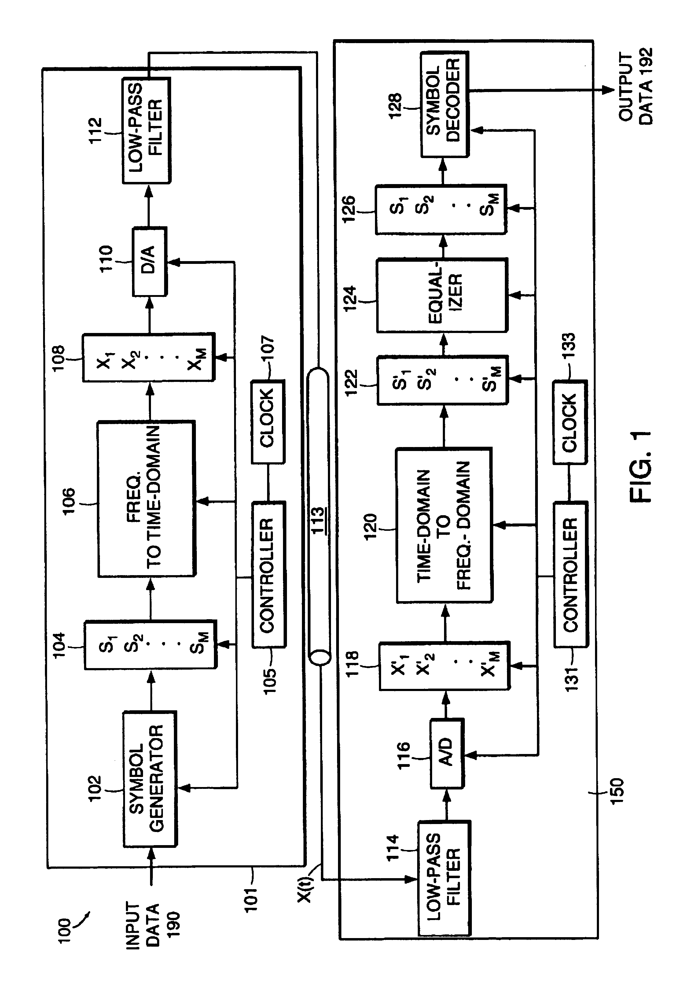
[0047]The manner in which the present invention operates can be more easily understood with reference to FIG. 1 which is a block diagram of a typical prior art multi-carrier transceiver 100. Transceiver 100 transmits data on a communication link 113. The input data stream is received by a symbol generator 102 which converts a run of data bits from the input stream into M symbols S1, S2, . . . , SM which are stored in a register 104. The number of possible states for each symbol will depend on the noise levels in the corresponding frequency band on the transmission channel 113 and on the error rate that can be tolerated by the data. For the purposes of the present discussion, it is sufficient to note that each symbol is a number whose absolute value may vary from 0 to some predetermined upper bound. For example, if a symbol has 16 possible values, this symbol can be used to represent 4 bits in the input data stream.

[0048]Transceiver 100 treats the symbols Si as if they were the ampli...


PUM


Abstract

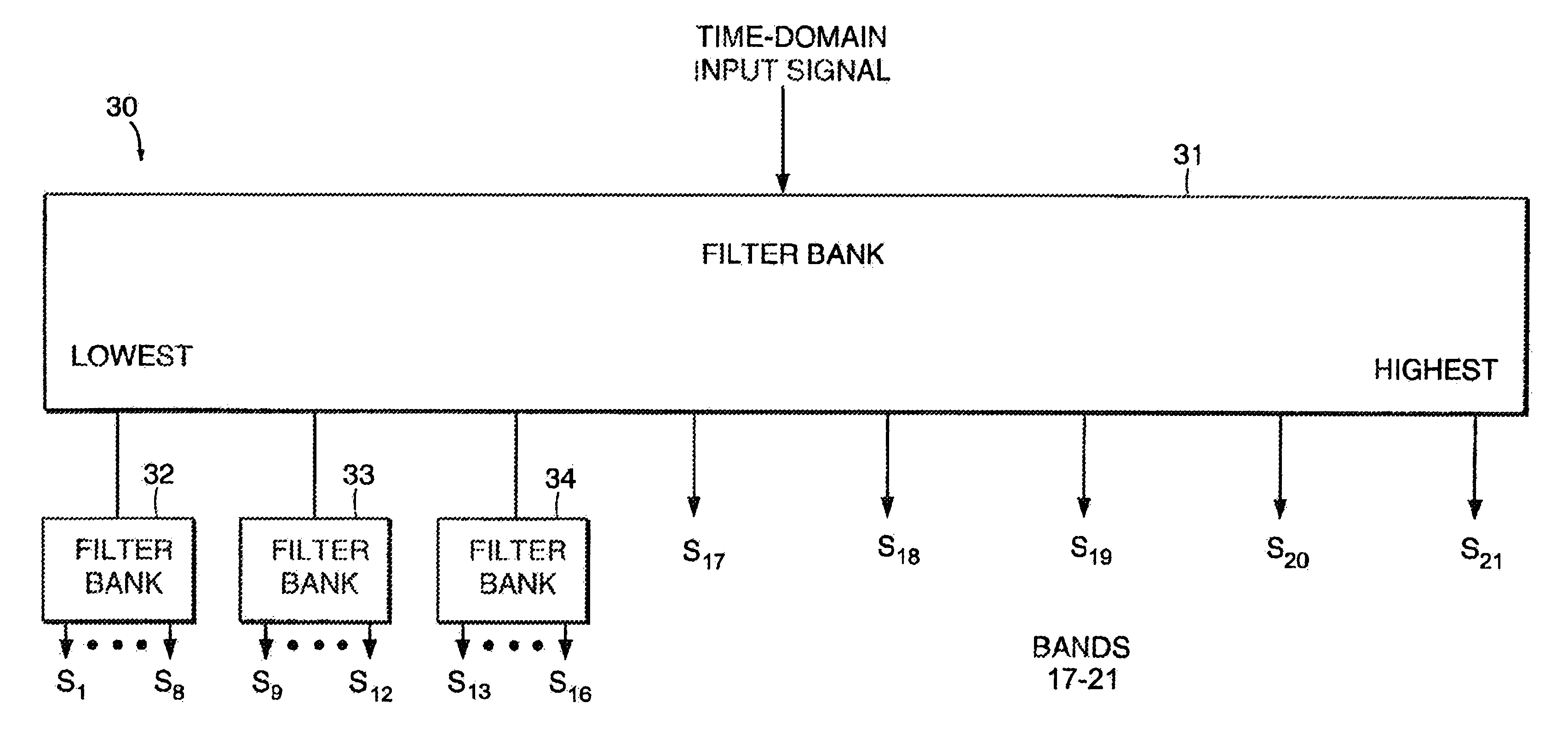
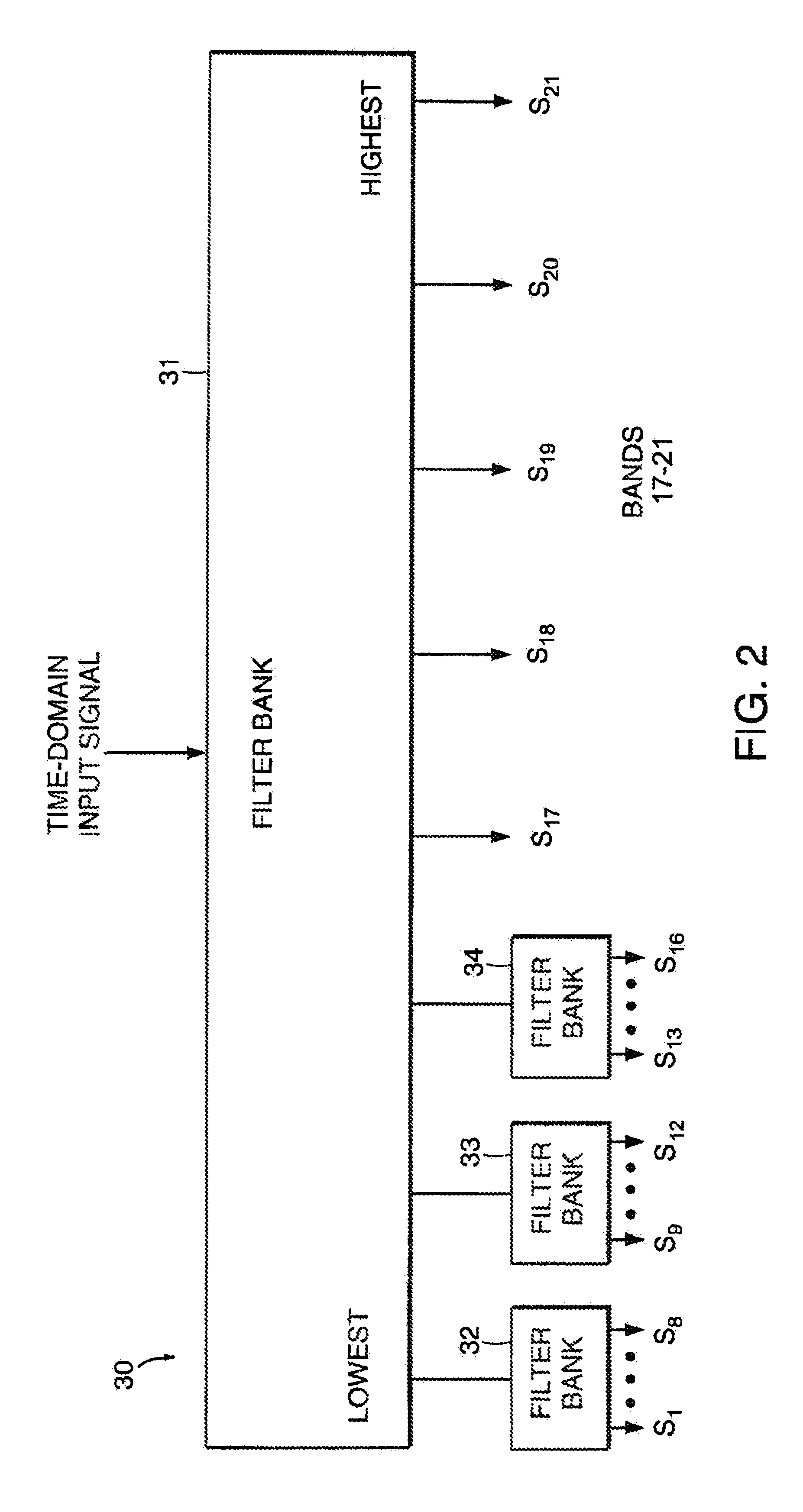
A communication system for sending a sequence of symbols on a communication link. The system includes a transmitter for placing information indicative of the sequence of symbols on the communication link and a receiver for receiving the information placed on the communication link by the transmitter. The transmitter includes a clock for defining successive frames, each of the frames including M time intervals, where M is an integer greater than 1. A modulator modulates each of M carrier signals with a signal related to the value of one of the symbols thereby generating a modulated carrier signal corresponding to each of the carrier signals. The modulated carriers are combined into a sum signal which is transmitted on the communication link. The carrier signals include first and second carriers, the first carrier having a different bandwidth than the second carrier. In one embodiment, the modulator includes a tree-structured array of filter banks having M leaf nodes, each of the values related to the symbols forming an input to a corresponding one of the leaf nodes. Each of the nodes includes one of the filter banks. Similarly, the receiver can be constructed of a tree-structured array of sub-band filter banks for converting M time-domain samples received on the communication link to M symbol values.Signal processing is performed by splitting a signal into subbands using a plurality of filter banks connected to form a tree-structured array. The filter banks are connected so that the signal is split into subbands of different size. The subbands can be designed to approximate the bands of the human auditory system for audio signal processing applications. Reconstruction of signals using a plurality of synthesis filter banks connected to form a tree-structured array is also performed.

Description

[0001]This applicationThis application is a Division of U.S. Reissue application No. 10 / 603,833 filed Jun. 26, 2003, now abandoned, which is a Reissue of U.S. application No. 08 / 804,909, filed Feb. 25, 1997, now U.S. Pat. No. 6,252,909, issued Jun. 26, 2001. U.S. application No. 08 / 804,909, filed Feb. 25, 1997, is a Continuation-in-Part of U.S. patent application Ser. No. 08 / 307,331, filed Sep. 16, 1994, Pat. No. 5,606,642, which is a division of U.S. Patent Application Ser. No. 07 / 948,147, filed Sep. 21, 1992, Pat. No. 5,408,580.FIELD OF THE INVENTION[0002]The present invention relates to data transmission systems, and more particularly, to an improved multi-carrier transmission system. The present invention further relates to audio compression and decompression systems.BACKGROUND OF THE INVENTION[0003]In prior art multi-carrier systems, a communication path having a fixed bandwidth is divided into a number of sub-bands having different frequencies. The width of the sub-bands is ch...

Claims


Application Information

Patent Timeline
IPC IPC(8): G10L19/02H03D1/24H04B1/38H04K1/10G10L19/00H04B1/66
CPCG10L19/008H04B1/665
Inventor TZANNES, MICHAEL A.HELLER, PETER N.STAUTNER, JOHN P.MORRELL, WILLIAM R.JAYASIMHA, SRIRAM
Owner HYBRID AUDIO
Learn More