Method and system for removing fuel oil thiophen sulfide
A technology of sulfide and fuel oil, applied in the petroleum industry, refining hydrocarbon oil, etc., to achieve mild regeneration conditions, mild desulfurization conditions, and simple processes and equipment
- Summary
- Abstract
- Description
- Claims
- Application Information
AI Technical Summary
Problems solved by technology
Method used
Image
Examples
Embodiment 1
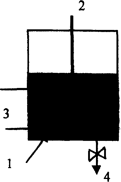
[0021] Embodiment 1: Catalyst NaOH and reactant formaldehyde are pre-placed in the hole of activated carbon to make desulfurizer, and formaldehyde is 50% of activated carbon weight, and NaOH is 80% of activated carbon weight. Put the suspension 1 composed of one ton of fuel oil and 50kg of desulfurizer into the figure 1 In the shown tank reactor, the temperature of the reaction mixture is maintained at 90°C by the stirrer 2 and the heating coil 3, and the stirring is continued until the sampling and analysis of the oil product shows that the fuel oil has no sulfur, and then the operation is stopped. The material is released from the discharge port 4, and sent to the filter to filter out the saturated desulfurizing agent to obtain clean fuel, and the desulfurizing agent is regenerated. To this end, return the saturated desulfurizer to the reaction kettle, add solvent ethanol, stir at room temperature for a certain period of time, release the material, and send it to a filter fo...
Embodiment 2
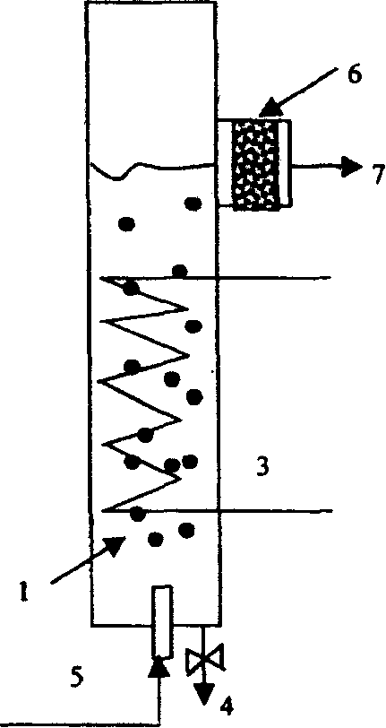
[0022] Embodiment 2: Catalyst H 2 SO 4 and the reactant formaldehyde are pre-placed in the pores of the activated carbon to make a desulfurizer, the formaldehyde is 10% of the weight of the activated carbon, and the H 2 SO 4 60% of the weight of activated carbon. Put 50kg desulfurizer in the attached figure 2 In the fluidized bed reactor shown, sulfur-containing fuel oil 5 enters the reactor from the bottom of the reactor, and its flow rate makes the desulfurizing agent in a fluidized state to form a suspension 1 of fuel oil and desulfurizing agent, and the heating coil 3 ensures that the suspension reaches 70 ℃, clean fuel oil 7 flows out through the filter 6 at the top of the reactor. Monitor the sulfur content of the fuel oil flowing out of the tower top. Under normal operating conditions, the sulfur content of the fuel oil flowing out of the top of the tower is zero. If the sulfur content rises, it means that the desulfurizer in the tower is saturated, stop the opera...
Embodiment 3
[0023] Embodiment 3: Catalyst HCL and reactant acetaldehyde are pre-placed in the pores of activated carbon to make desulfurizer, formaldehyde is 20% of the weight of activated carbon, and HCL is 40% of the weight of activated carbon. Pack 50 kg of desulfurizer in the attached image 3 In the fixed bed reactor shown. The sulfur-containing fuel oil 5 flows down from the top of the reactor, and is clean fuel oil after flowing out from the bottom of the adsorption tower through the discharge port 4 . The heating coil 3 maintains the desulfurizer bed temperature to 80°C. Monitor the sulfur content of the fuel oil flowing out of the bottom of the tower. Under normal operating conditions, its sulfur content is zero. If the sulfur content rises, it means that the desulfurizer in the tower has been saturated. Stop the operation and enter the desulfurizer regeneration operation. Another one that has just completed desulfurizer regeneration is exactly the same as this one. The reacto...
PUM
 Abstract
Description
Claims
Application Information
 - R&D
- Intellectual Property
- Life Sciences
- Materials
- Tech Scout
- Unparalleled Data Quality
- Higher Quality Content
- 60% Fewer Hallucinations
Browse by: Latest US Patents, China's latest patents, Technical Efficacy Thesaurus, Application Domain, Technology Topic, Popular Technical Reports.
© 2025 PatSnap. All rights reserved.Legal|Privacy policy|Modern Slavery Act Transparency Statement|Sitemap|About US| Contact US: help@patsnap.com


