Ultrasonic soldering equipment for solar cell electrode
A solar cell and ultrasonic welding technology, which is applied to welding equipment, non-electric welding equipment, metal processing equipment, etc., can solve the problems of poor welding quality and low welding efficiency, and achieve the effects of improving welding efficiency, eliminating virtual welding, and consistent spacing
- Summary
- Abstract
- Description
- Claims
- Application Information
AI Technical Summary
Problems solved by technology
Method used
Image
Examples
example 1
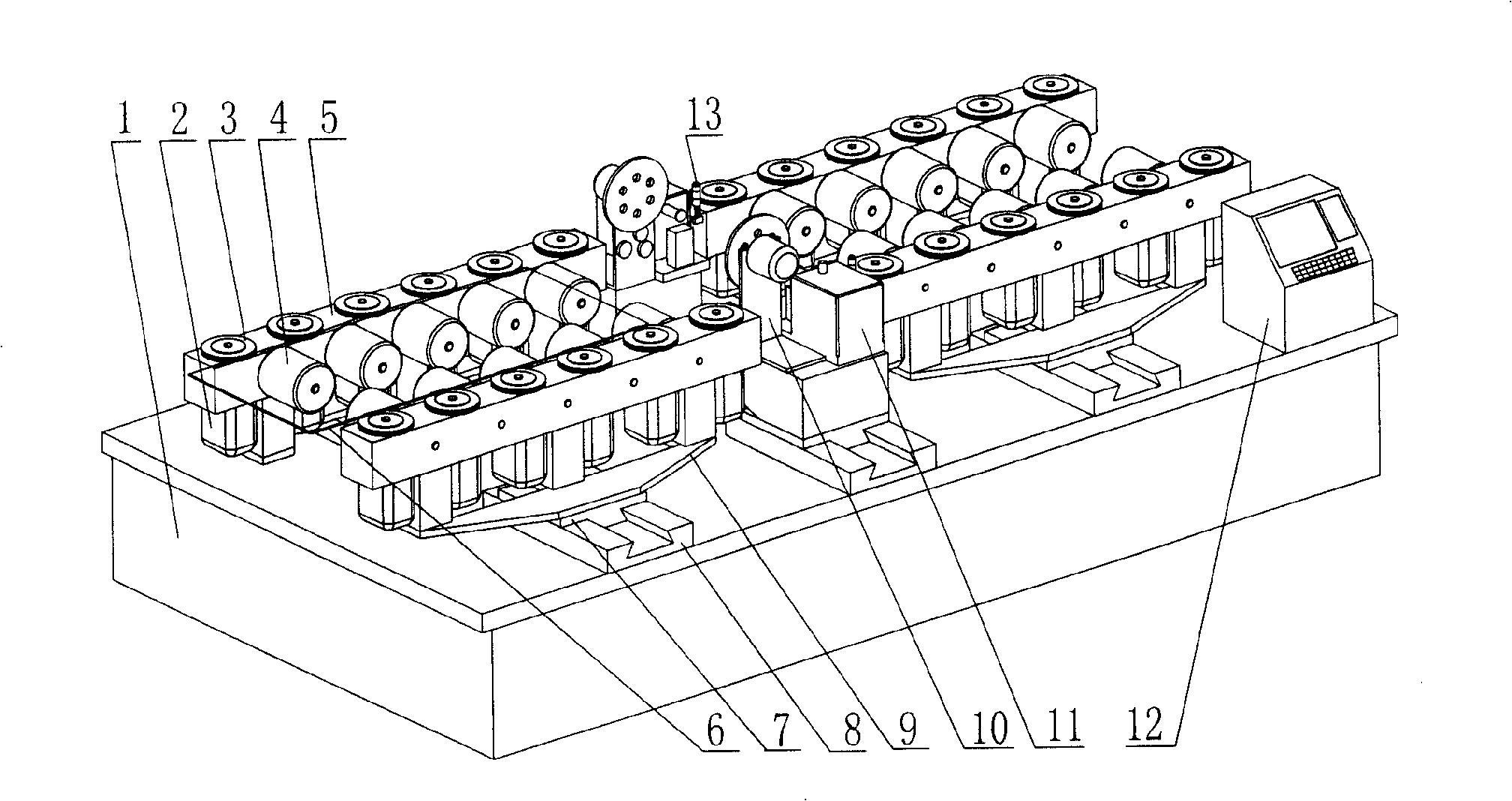
[0055] Example 1, see embodiment 1 of the present utility model such as figure 1 As shown, the electrode wire is made of metallic aluminum coated tin strip with a thickness of 2 mm and a width of 0.3 mm. The solar cell 6 is an amorphous silicon solar cell based on glass. Under the control of the PLC system, the feeding area sends the amorphous silicon solar cell to the ultrasonic welding area through the transmission device. The tin-coated strip with a width of 0.3 mm is stretched, compressed, and flattened. The metal welding head is welded with a welding pressure of 2MPa and a welding power of 110W. After the electrode welding is completed, the battery of the conveyor device is sent to the automatic wire cutting device 13 to cut off the tin-coated strip, and then the material is discharged. High welding efficiency, smooth solder joints and good appearance. Cooperating with automatic production lines, it can continuously feed, weld and discharge materials.
[0056] The guide...
example 2
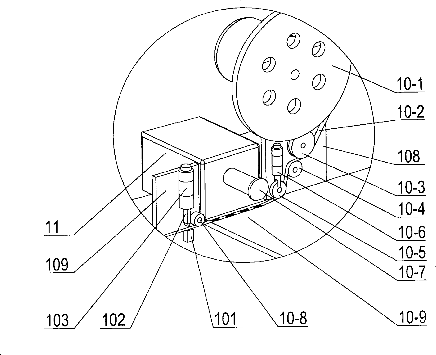
[0057] Example 2, the overall structure of this embodiment is the same as Example 1, see Figure 1 to Figure 8 , on the workbench 1, install the solar cell transmission device, the electrode wire pay-off and pressing device 10, the ultrasonic metal spot welding machine 11, the thread cutting device 13 and the PLC numerical control system 12 in order from left to right. The main process steps are as follows: the first step is to arrange the solar cells on the workbench 1; the second step is to drive the solar cells by the transmission device to realize linear feeding; release; pressing and welding on the solar cell; the fourth step, the wire cutting device 13 cuts off the electrode wire.
[0058] In the transmission device, with the installation method of symmetrical arrangement, the rotating shaft of the stepping motor 2 passes through the center hole of the positioning roller 3, and the shafts and holes of the two are connected by interference fit; the stepping motor 2 is ins...
example 3
[0062] Example 3, the technical process of the present invention are as follows:
[0063] 1) Adjust the bracket 9 so that the distance between the positioning rollers 3 arranged symmetrically along the two sides matches the width of the amorphous silicon solar cell;
[0064] 2), PLC controls the stepper motor 2 to work, drives the positioning roller 3 to rotate, and drives the amorphous silicon solar cell 6 to enter the welding area;
[0065] 3), the wire-releasing and pressing device presses the electrode wires on the amorphous silicon solar cell: Step 1, the stepper motor 2 decelerates, and the amorphous silicon solar cell 6 continues to feed;
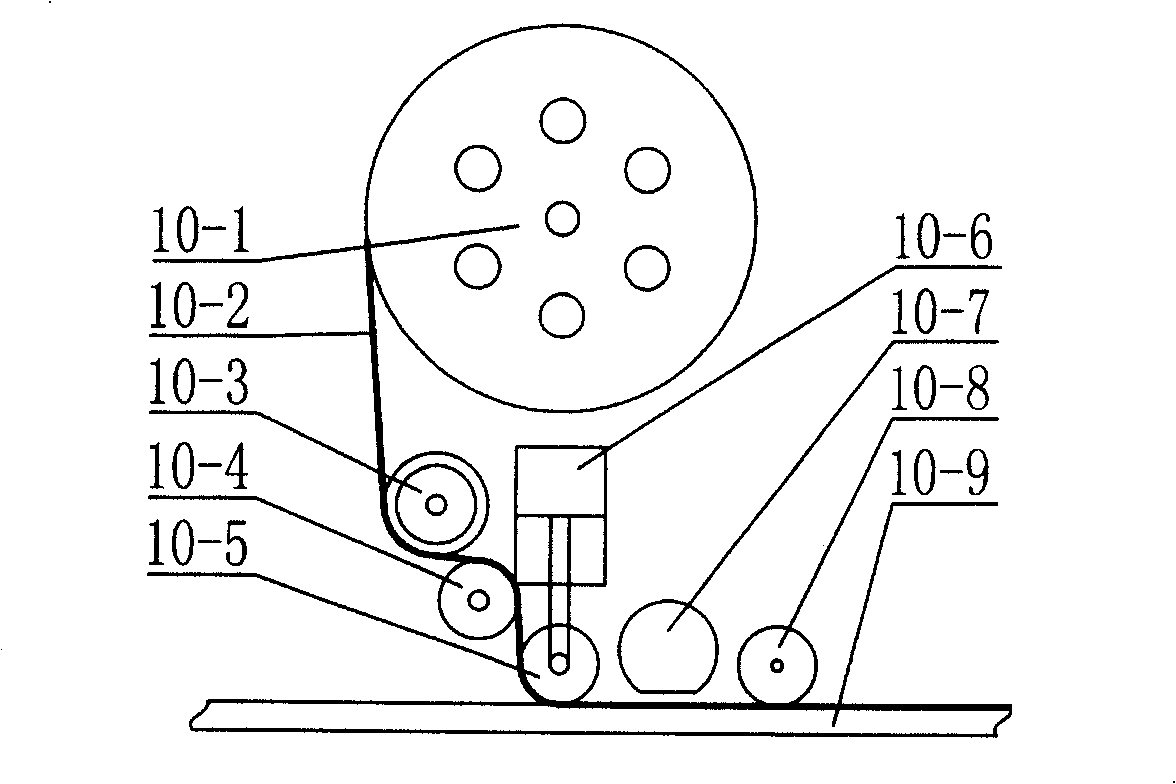
[0066] Step 2, under the control of the PLC, the cylinder stretches out the telescopic rod 10-6-1, and the crimping wheel 10-5 connected to the telescopic rod 10-6-1 presses the electrode wire 10-2 to the amorphous silicon solar cell 6 superior;
[0067] Step 3, the electrode wire 10-2 is affected by the friction force of the wire ...
PUM
| Property | Measurement | Unit |
|---|---|---|
| thickness | aaaaa | aaaaa |
| width | aaaaa | aaaaa |
Abstract
Description
Claims
Application Information
 - R&D
- Intellectual Property
- Life Sciences
- Materials
- Tech Scout
- Unparalleled Data Quality
- Higher Quality Content
- 60% Fewer Hallucinations
Browse by: Latest US Patents, China's latest patents, Technical Efficacy Thesaurus, Application Domain, Technology Topic, Popular Technical Reports.
© 2025 PatSnap. All rights reserved.Legal|Privacy policy|Modern Slavery Act Transparency Statement|Sitemap|About US| Contact US: help@patsnap.com


