Device for producing small solder alloys welding balls
A technology for manufacturing devices and brazing filler metals, which is applied to welding media, manufacturing tools, and welding equipment. It can solve problems such as high manufacturing costs, low solder ball precision, and large equipment, and achieve bright surfaces, low oxygen content, and simplified structures. Effect
- Summary
- Abstract
- Description
- Claims
- Application Information
AI Technical Summary
Problems solved by technology
Method used
Image
Examples
specific Embodiment approach 1
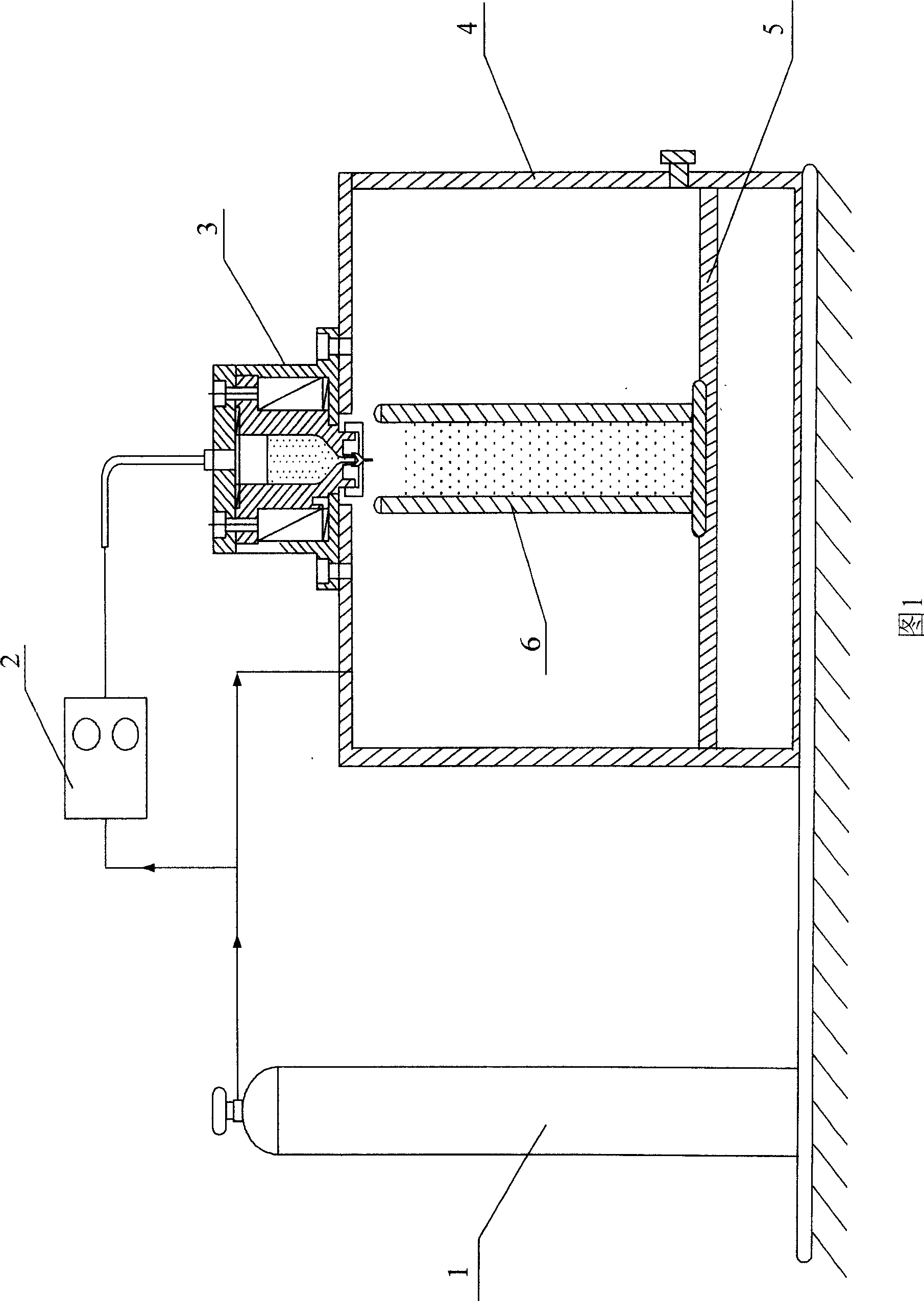
[0014] Specific Embodiment 1: The present embodiment will be described in detail below in conjunction with FIG. 1 . This embodiment is composed of a gas supply device 1, a pressure controller 2, a droplet generator 3, a gas protection device 4, an elevating work platform 5 and a cooling and solidification device 6 , the gas output end of the gas supply device 1 is respectively connected to the input end of the pressure controller 2 and the top of the gas protection device 4, the output end of the pressure controller 2 is connected to the inlet end of the droplet generator 3, and the droplet generator 3 is fixed on the top of the gas protection device 4 by screws, the central part of the droplet generator 3 communicates with the inside of the gas protection device 4, and the lifting working platform 5 is set at the lower part of the gas protection device 4 and can move up and down, and is cooled and solidified The device 6 is installed on the lifting working platform 5 in the ga...
specific Embodiment approach 2
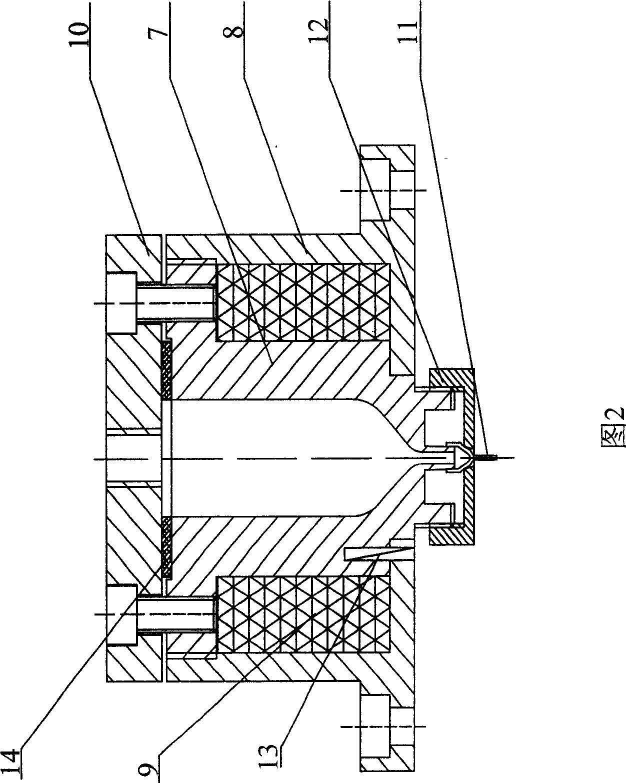
[0015] Specific embodiment two: below in conjunction with Fig. 2 specific description present embodiment, present embodiment drop generator 3 is made of stainless steel crucible 7, sleeve 8, heating wire 9, top cover 10, nozzle 11, gland 12 and thermocouple 13 Composition, the sleeve 8 is set on the outside of the stainless steel crucible 7, a heating wire 9 is arranged between the sleeve 8 and the stainless steel crucible 7, the sleeve 8 is fixed on the gas protection device 4 by fastening screws, and the top cover 10 is tightened by The solid screw is fixed on the top of the stainless steel crucible 7 and the sleeve 8. There is a gas inlet on the upper side of the top cover 10. The space between the top cover 10 and the stainless steel crucible 7 is sealed by a gasket 14. The bottom of the stainless steel crucible 7 is provided with a nozzle 11. The gland 12 passes through the nozzle 11 and is placed on the bottom of the stainless steel crucible 7. A thermocouple 13 is built ...
specific Embodiment approach 3
[0016] Specific implementation mode three: this implementation mode is completed by the following steps:
[0017] Step 1: Add solid solder into the stainless steel crucible 7 of the droplet generator 3, and fasten the top cover 10;
[0018] Step 2: Select the type of nozzle 11 and tighten the gland 12. The air in the gas protection device 4 is evacuated and filled with argon or nitrogen; using a reduced-diameter nozzle, the molten solder solution flows through the reduced diameter to force the diameter to be reduced. According to Lap Lars' theorem, the smaller the radius of curvature, the greater the additional pressure generated by surface tension; the smaller the radius of curvature at the constriction, the greater the downward additional pressure; and the larger the radius of curvature, the smaller the additional pressure, In this way, the solder flows from the place with high pressure to the place with low pressure, which intensifies the fracture of the liquid solder colum...
PUM
 Abstract
Description
Claims
Application Information
 - R&D
- Intellectual Property
- Life Sciences
- Materials
- Tech Scout
- Unparalleled Data Quality
- Higher Quality Content
- 60% Fewer Hallucinations
Browse by: Latest US Patents, China's latest patents, Technical Efficacy Thesaurus, Application Domain, Technology Topic, Popular Technical Reports.
© 2025 PatSnap. All rights reserved.Legal|Privacy policy|Modern Slavery Act Transparency Statement|Sitemap|About US| Contact US: help@patsnap.com


