Pipe pressure sensor

A tube pressure sensor and sensor technology, used in instruments, fluid pressure measurement using piezoelectric devices, machines/engines, etc., can solve problems such as unfavorable on-site use, complex parameter adjustment, waste, etc., to save hardware costs, anti-interference Powerful, wide filtering effects

Inactive Publication Date: 2010-01-13
张小明
View PDF4 Cites 0 Cited by
  • Summary
  • Abstract
  • Description
  • Claims
  • Application Information

AI Technical Summary

Problems solved by technology

From a structural point of view, the diameter of the oil pipe measured by the sensor must be exactly the same as that of the sensor, and it has high requirements on the smoothness and shape of the outer surface of the oil pipe. Moreover, due to its large size, it requires a certain installation space, which is not conducive to actual vehicle testing.
In addition, it needs to be equipped with charge amplifier and filter to use
[0003] Comprehensive analysis shows that the current pipe pressure sensors generally have the following problems: 1. The clamping is not convenient enough, and the requirements for the oil pipe to be tested are relatively high; lack of flexibility: a sensor can only test oil pipes of one diameter, and the pipe diameter commonly used in diesel engines Φ6, Φ7, Φ8, and the diameter of the hydraulic oil pipe is available in various sizes from Φ6 to Φ35. In this way, a large number of sensors of different types are required, resulting in great waste
2. The overall size is large, so it is not suitable for testing the oil pipe pressure in a narrow space
The sensor needs to be equipped with a high-performance charge amplifier and filter before it can be used, and the parameter adjustment is relatively complicated, not universal, and not conducive to field use in real vehicles
Due to certain limitations in the setting of the external filter, the test waveform filtering is not perfect, which will affect the subsequent data analysis and feature extraction
3. In terms of fastening methods, some sensors have unreasonable fastening methods, and the sensors are easy to loosen and fall off; some sensors have high requirements for the stiffness of the locking rod, and too high or too low stiffness will affect the use of the sensor
4. The clamping positioning is not unique, and the radial force of the oil pipe deformation cannot directly act on the force-bearing surface of the sensor, resulting in deviation of the test results

Method used


Image

  • Pipe pressure sensor
  • Pipe pressure sensor

Examples


Embodiment

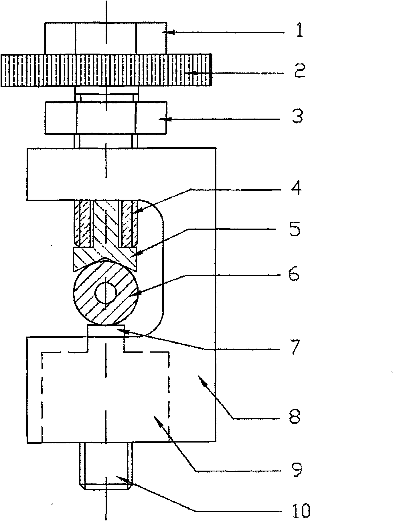
[0012] Such as figure 1 As shown, the sensor housing 8 is "匚" shaped, and the upper end has a screw hole that can be screwed into the fastening bolt 4. The fastening bolt 4 has a fastening bolt hexagonal bolt head 1 and a fastening bolt circular bolt head 2 with outer circle knurling, and a hexagonal locking nut 3 is also arranged on the fastening bolt. There is a deep hole at the bottom of fastening bolt 4, and the positioning pressure block 5 of inverted " T " shape is installed in it with sliding fit. The "herringbone"-shaped bottom surface of the positioning pressure block 5 and the force-bearing surface 7 of the sensor form a triangular positioning card on the oil pipe 6 to be tested. The sensor body is mounted on the bottom of the sensor housing 8, and the sensor body 9 and the sensor housing 8 are connected by threads and glued together. The signal output terminal 10 outputs the test signal. When in use, first clamp the pipe pressure sensor on a suitable position of ...


PUM

PropertyMeasurementUnit
Sensitivityaaaaaaaaaa

Abstract

The invention provides an outer-locking ICP-type pipe-pressure sensor which is rational-structured, convenient and reliable to install, small-volume, and suitable for present space-compacted oil pipe pressure test. The foundational working principle of the sensor is the piezoelectricity effect; the sensor is suitable for dynamic pressure test; the said novel pipe-pressure sensor is composed of a sensor body, a shell, a modulating module. The sensor is mainly composed of a piezoelectricity crystal, an integral circuit amplifier, a signal output end and a stress surface; the sensor shell is composed of a shell, fastened bolts, locking screw caps, positioning blocks; the modulating module is composed of a constant flow resource and an external amplifying circuit. The novel pipe-pressure sensor provided by this invention, has sensibilities of 1000mV / N, 100m / N , measuring ranges of 5N, 50N; sensor of testing pipe diameter as diesel engine high-pressure oil pipe is Phi6-Phi8, the sensor of hydraulic oil pipe is no more than Phi 22, and Phi 35.

Description

technical field [0001] The invention relates to a dynamic pressure measuring instrument in an oil pipe, in particular to a pipe pressure sensor for measuring the pressure wave of a high-pressure oil pipe of a diesel engine and a hydraulic oil pipe. Background technique [0002] As we all know, the quality of the working process of the fuel injection system directly affects the performance of the diesel engine such as power, emission, fuel economy and work reliability, and its serious failure will cause the diesel engine to lose its working ability. Therefore, since the 1970s, researchers have carried out a lot of work on the fault diagnosis of diesel fuel injection system. It is a relatively intuitive method to identify fuel injection system faults and calculate fuel supply-related parameters by analyzing the pressure waveform of the high-pressure fuel pipe. In addition, with the rapid development of hydraulic technology, the fault diagnosis of hydraulic system is becoming ...

Claims


Application Information

Patent Timeline
Patent Type & Authority Patents(China)
IPC IPC(8): G01L9/08F02M65/00
Inventor 张小明刘建敏安钢乔新勇
Owner 张小明
Why Eureka
Try Eureka