Integral gradient self-lubricating bearing, and fabricating method

A self-lubricating bearing and solid lubrication technology, applied in bearing components, shafts and bearings, mechanical equipment, etc., can solve the problems of metal bushings requiring drilling, unfavorable environmental protection, complex manufacturing processes, etc., to achieve service life and overall mechanical properties. Improve, relieve thermal stress, enhance the effect of pressure

Inactive Publication Date: 2007-12-26
UNIV OF SCI & TECH BEIJING
View PDF0 Cites 17 Cited by
  • Summary
  • Abstract
  • Description
  • Claims
  • Application Information

AI Technical Summary

Problems solved by technology

[0004] (1) Metal-based inlaid solid self-lubricating bearings are loaded by a metal base, and solid lubricating materials are embedded in the base for lubrication. The disadvantage is that the metal bushing needs to be drilled, and it is difficult to process the miniature bushing. Large; the lubricant is mechanically filled, and it is not easy to form a complete lubricating surface during work [Zhang Guoxing. Composite materials for modern sliding bearings. Mechanical Engineers, 2005, 9: 114~115]
The disadvantage of this method is that the manufacturing process is complicated, and the structure and performance of the ferrule are difficult to meet the requirements of use [Jin Zhuoren et al. Development of gradient self-lubricating sliding bearings. Chinese Journ

Method used


Image

  • Integral gradient self-lubricating bearing, and fabricating method
  • Integral gradient self-lubricating bearing, and fabricating method

Examples


Example Embodiment

[0034] Example 1:

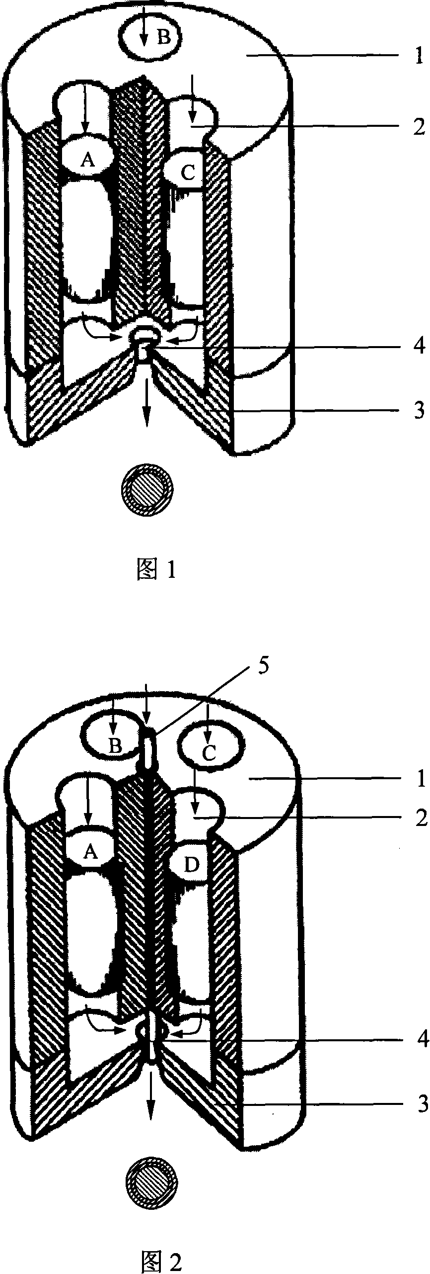
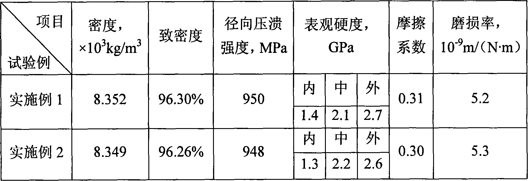
[0035] The material ratio is expressed in volume percentage: 100% stainless steel in the pressure-bearing layer; 10% molybdenum disulfide and 90% tin bronze in the solid lubricating layer; 8% molybdenum disulfide, 60% tin bronze and 32% stainless steel in the transition layer. The particle size of the molybdenum disulfide powder is 3 to 5 μm, the particle size of the tin bronze powder is 30 to 40 μm, and the particle size of the stainless steel powder is 8 to 12 μm. After the powders of each layer are uniformly mixed in proportion, the binder (mixed powder 95 wt%, binder 5 wt%) is added. The binder is composed of HPMC (content 10wt%) and deionized water (content 90wt%). After mixing into a powder viscous body, seal and wrap it with plastic wrap, and store it at room temperature for 10-24 hours. The powder viscous body is made into a pre-extrusion according to the size of the extrusion cylinder. The pre-extrusion blanks of each layer are put into the extrusion c...

Example Embodiment

[0036] Example 2:

[0037] The material ratio is expressed by volume percentage: pressure-bearing layer stainless steel 100%; solid lubricating layer 15% molybdenum disulfide, tin bronze 85%; transition layer molybdenum disulfide 6%, tin bronze 54%, stainless steel 40%. The particle size of the molybdenum disulfide powder is 3-5μm, the particle size of the tin bronze powder is 30-40μm, and the particle size of the stainless steel powder is 8-12μm; the pressure-bearing layer is directly made of stainless steel bars. After the solid lubricating layer and the transition layer powder are evenly mixed in proportion, the binder (mixed powder 97 wt%, binder 3 wt%) is added. The binder is composed of HPMC (content 8wt%) and deionized water (content 92wt%). After mixing into a powder viscous body, it is sealed and wrapped with plastic wrap, and stored at room temperature for 10 to 32 hours. The powder viscous body is made into a pre-extrusion according to the size of the extrusion cylinder...


PUM


Abstract

This invention relates to an integral grad self-lubricating bearing and its manufacturing method, in which the bearing is composed of a bearing layer, a lubricating layer and a transition layer in the middle, and the bearing layer is made up of carbon steel, stainless steel or bearing steel, the lubricating layer is mixed by a solid lubricating matrix material and a solid lubricant, and the matrix is made of bronze or brass, the solid lubricant is made of MoS2, Sn or graphite, the matrix material is mixed with the solid lubricant to form a solid lubricating layer, the middle transition layer is formed by mixing the bearing material and the solid lubricating material in proportion, which has higher intensity, better rub-reduction and better integration.

Description

technical field [0001] The invention relates to the field of self-lubricating bearings, and in particular provides an integral gradient self-lubricating bearing and a manufacturing method thereof. Background technique [0002] Bearings are a very common and critical type of parts used in industry, and are known as the "joints" of machines. With the development of mechanical instruments and equipment in the direction of precision, miniaturization, long life, and high performance, as well as complex and harsh working conditions such as high temperature, high speed, heavy load, vacuum, and oil-free lubrication, the current use of Traditional external oil-lubricated bearings and ordinary self-lubricating bearings have been difficult to meet the requirements. [0003] So people developed a series of new self-lubricating oil-free bearings: [0004] (1) Metal-based inlaid solid self-lubricating bearings are loaded by a metal base, and solid lubricating materials are embedded in t...

Claims


Application Information

Patent Timeline
IPC IPC(8): F16C33/10F16C33/12F16C33/14
Inventor 刘雪峰谢建新赵劲松
Owner UNIV OF SCI & TECH BEIJING
Why Eureka
Try Eureka