Exhaust pipe for motorboat engine

A motorboat and engine technology, which is applied to engine components, machines/engines, propulsion engines, etc., can solve the problems of the motorboat's shell becoming soft, losing the function of driving, interfering with gas, etc., to reduce the number, intermediate Fewer links and noise reduction effect

Inactive Publication Date: 2008-02-13
CHERY AUTOMOBILE CO LTD
View PDF3 Cites 10 Cited by
  • Summary
  • Abstract
  • Description
  • Claims
  • Application Information

AI Technical Summary

Problems solved by technology

Therefore, the normal working condition of the motorboat engine is above 4000rpm, and the maximum can reach 8000rpm. The exhaust temperature of the engine is generally above 750°C, and the maximum even reaches 860°C. A large amount of heat is produced, which makes the temperature in the engine compartment rise rapidly. If the large amount of heat cannot be dissipated as soon as possible, not only the peripheral parts of the engine will fail, the shell of the motorboat will become soft and lose the function of driving, and it will cause a fire. , causing serious consequences
[0005] Chinese patent No. is that the patent documentation of CN89109742.2 discloses a kind of exhaust pipe of multi-cylinder piston internal combustion engine; The patent literature of CN02107833.5 discloses a two-layer exhaust pipe inside and outside; and such related patent technologies and literature materials mainly consider the strength and stability of the exhaust pipe, avoiding the mutual interference of each cylinder, and the noise reduction of the gas itself. , all do not involve interlayer water cooling and noise reduction technology. Therefore, it is difficult for the existing known technology to meet the requirements when using motorboats, which are easy to quickly generate high temperatures and have strict restrictions on temperature rise.

Method used


Image

  • Exhaust pipe for motorboat engine

Examples


Embodiment 1

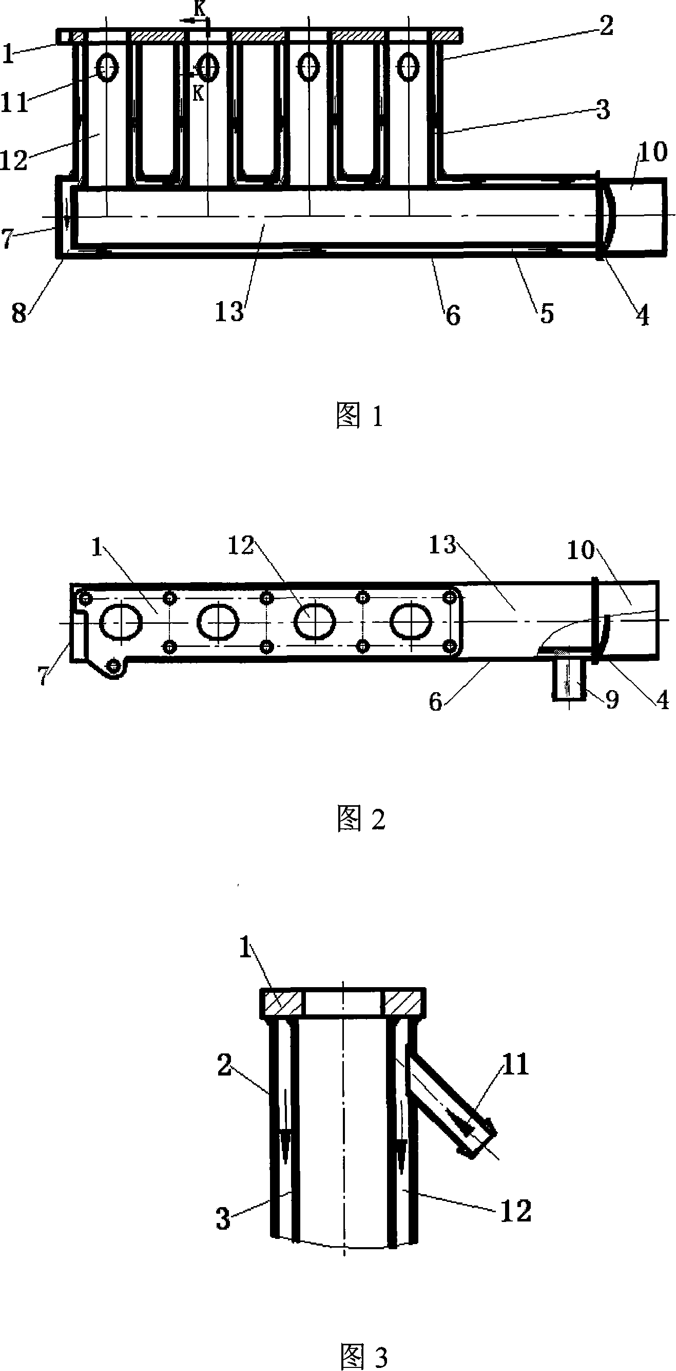
[0041] The nozzle of described exhaust tail pipe 10 stretches out of the hull of motorboat.

Embodiment 2

[0043] The nozzle of the exhaust tailpipe 10 is in the hull of the motor boat, and a water vapor collection box is arranged at the nozzle of the exhaust tailpipe 10 .

[0044] As shown in Figure 3, in order to make the water flow into the cavity to fill the inner cavity, the connection method between the water inlet port 11 and the outer pipe 6 of the main pipe is: the water inlet direction of the water inlet port 11 has a direction pointing to the connecting surface of the engine. slope. After the water flow enters, at first the exhaust pipe flange 1 with the highest temperature is fully cooled. The arrows in the figure indicate the direction of water flow.

[0045] To sum up, the exhaust pipe involved in the present invention adopts an inner and outer two-layer stainless steel exhaust manifold 12, an exhaust main pipe 13, four water inlet ports 11, one water outlet port 9, a sound-absorbing damping sheet assembly 4, and exhaust pipes. An assembly part welded by gas tail pi...


PUM


Abstract

The present invention discloses a vent pipe of an engine for a motorboat. An exhaust manifold (12) and an exhaust main (13) are double layer structure, that is, the exhaust manifold (12) consists of an external pipe of the manifold (2) and an internal pipe of the manifold (3) and the exhaust main (13) consists of an internal pipe of the exhaust main (5) and an external pipe of the exhaust main (6). The internal pipe of the manifold (3) and the internal pipe of the exhaust main (5) are connected to form a lining pipe body while the external pipe of the manifold (2) and the external pipe of the exhaust main (6) are connected to form an outer layer pipe body. A cavity is formed between the lining pipe body and the outer layer pipe body, that is, a channel for the cooling water. The technic proposal uses the flow of the seawater or the river water to cool the vent pipe, which can effectively reduce the temperature of the exhaust manifold and the exhaust main of the engine of the motorboat. The damp of the vapor can be discharged by a pore. The gas discharged by the vent pipe is silenced for the second time, which reduces the noise of the exhaust system and improves the amenity of the driving.

Description

technical field [0001] The invention belongs to the technical field of engines, and relates to its ventilation system, more specifically, the invention relates to an exhaust pipe of a motorboat engine. Background technique [0002] Usually, the exhaust manifold of the engine is made of compacted graphite cast iron or high-nickel cast iron, and the exhaust manifold of some engines is welded by single-layer stainless steel pipe. Due to the high exhaust temperature of modern engines, the general engine uses a heat shield to separate the exhaust temperature of the engine from the surrounding parts to prevent the exhaust temperature from scorching other objects and failing; and for the exhaust noise of the engine, generally Both front and rear mufflers are added to the whole vehicle to reduce the noise of the exhaust system. [0003] When the engine is running, the high-temperature gas discharged after combustion passes from the engine cylinder head to the waist-shaped holes of ...

Claims


Application Information

Patent Timeline
Patent Type & Authority Applications(China)
IPC IPC(8): B63H21/32F01N7/08F01N13/08
Inventor 冯武堂汪久高黄文田吴泽荣
Owner CHERY AUTOMOBILE CO LTD
Why Eureka
Try Eureka