Oscillatory type double roll strip casting mill

A twin-roll thin strip, cast-rolling machine technology, applied in the direction of metal rolling stand, metal rolling mill stand, fluid using vibration, etc., can solve problems such as segregation, cracks, delamination, easy deposition of impurities, etc., and achieve uniform distribution Effects of alloy composition, segregation reduction, and crack reduction

Inactive Publication Date: 2008-05-21
YANSHAN UNIV
View PDF0 Cites 10 Cited by
  • Summary
  • Abstract
  • Description
  • Claims
  • Application Information

AI Technical Summary

Problems solved by technology

[0002] At present, ordinary casting and rolling machines directly use casting rolls as crystallization rolls. When the casting and rolling machine is working, the two casting rolls roll synchronously.

Method used


Image

  • Oscillatory type double roll strip casting mill
  • Oscillatory type double roll strip casting mill
  • Oscillatory type double roll strip casting mill

Examples


Embodiment 1

[0016] Embodiment 1 mechanical vibration type twin-roll strip casting and rolling mill

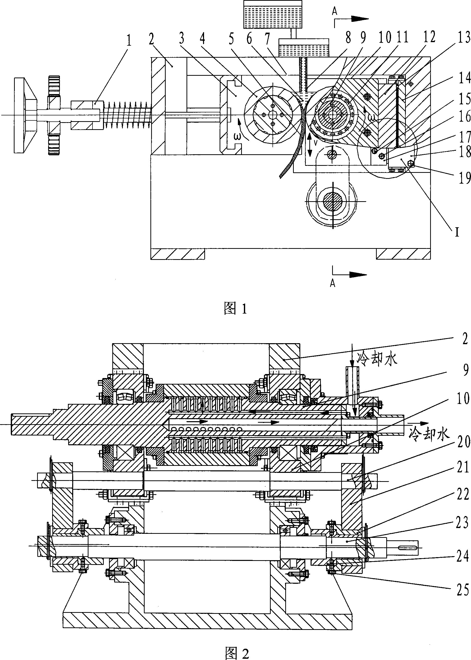
[0017] Fig. 1 is a mechanical vibrating twin-roll strip casting mill disclosed by the present invention. One end of the connecting rod 21 is sleeved on the vibration shaft 20, and the other end is sleeved on the rotating shaft 23, and the vibration shaft 20 is installed on the bottom of the vibration side bearing block 10 (see FIG. 2). A crank device is set on the rotating shaft 23, and the crank device is composed of an outer eccentric sleeve 22 and an inner eccentric sleeve 24, both of which have eccentricity, and are fixed together by screws 25 after a relative rotation of an angle to form an eccentricity Different cranksets.

[0018] The inner ring of bearing 11 is equipped with vibration side casting roll 9, and bearing 11 is installed in the vibration side bearing block 10. The casting roller 4 on the non-vibrating side is installed in the bearing seat 3 on the non-vibrating side, ...

Embodiment 2

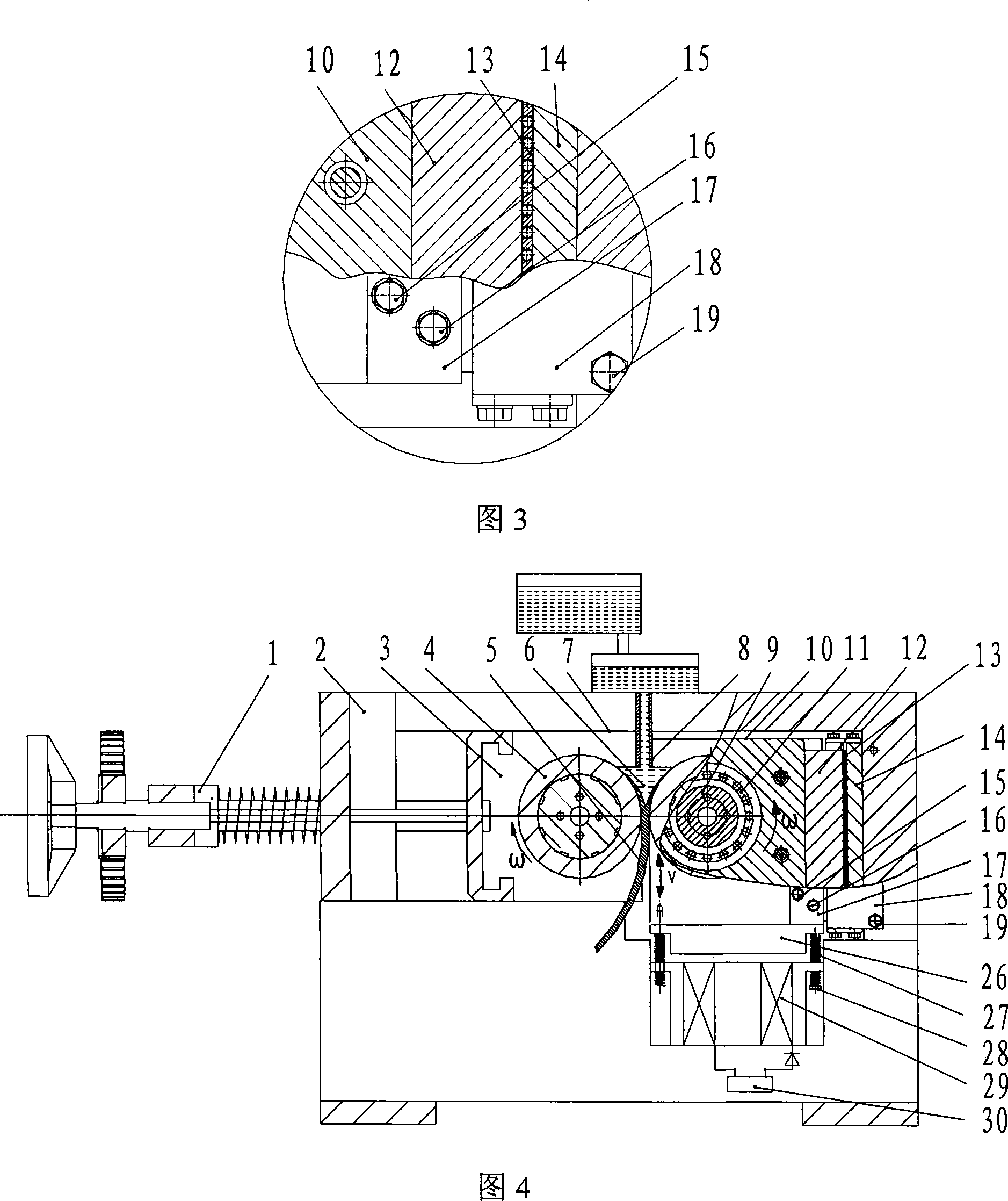
[0036] Embodiment 2 Electromagnetic vibration type twin-roll strip casting and rolling mill

[0037] As shown in FIG. 4 , the electromagnetic vibrating vibration device is mainly composed of an armature 26 , a spring 27 , an armature mandrel 28 , an electromagnetic coil 29 and a current regulator 30 . The armature mandrel 28 constrains the spring 27 and fixes the armature 26 and the vibration side bearing seat 10 together. The current regulator 30 controls the magnitude, direction and frequency of the current. Vibration side bearing seat 10 and its accessory parts move downward, and when electric current disappears, electromagnetic force also disappears, and vibration side bearing seat 10 moves up to original position under the effect of spring 27, has just finished a process of vibration like this. The amplitude and frequency of the armature 26 is controlled by a current regulator 30 .

Embodiment 3

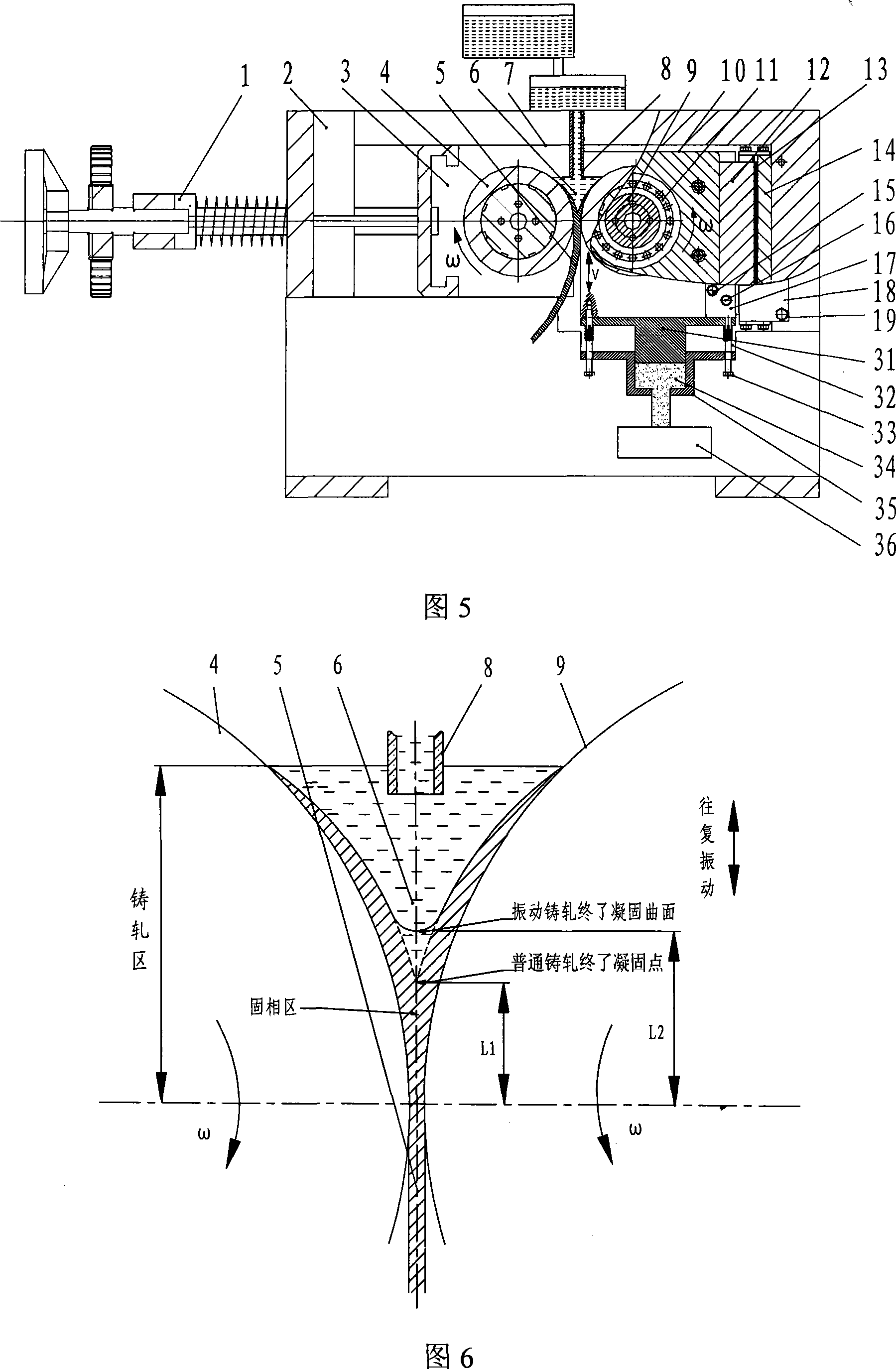
[0038] Embodiment 3 Hydraulic vibration type twin-roll strip casting and rolling mill

[0039] The hydraulic vibration device is mainly composed of a vibration piston 31, a spring 32, a mandrel 33, a hydraulic oil 34, a hydraulic cylinder 35, and a hydraulic servo system 36. The mandrel 33 fixes the vibrating side bearing housing 10 and the vibrating piston 31 together, the hydraulic cylinder 35 is fixed on the frame 2, the hydraulic oil 34 is controlled by the hydraulic servo system 36, and the vibration frequency and amplitude of the vibrating piston 28 are controlled by the hydraulic servo system 32 to control.

[0040] When the system works, the servo system 36 makes the hydraulic oil 34 flow to the hydraulic cylinder 35, and the hydraulic oil 34 is in a high-pressure state. At a certain position, the servo system 36 makes the hydraulic oil 34 flow out of the hydraulic cylinder 35, and when the hydraulic oil 34 is in a low-pressure state, the bearing housing 10 on the vib...


PUM


Abstract

The invention discloses a vibrating twin-roll thin strip casting machine, which is characterized in that: a pressing mechanism (1) is connected with a non-vibrating side bearing seat (3) equipped with a non-vibrating side casting roll (4), and the non-vibrating side bearing The seat (3) is installed on the slide rail (7) of the frame (2), the bearing (10) of the casting roll (9) on the vibration side is installed in the bearing seat (10) on the vibration side, and the bearing seat (3) on the non-vibration side ) and the vibration side bearing seat (10) are placed horizontally on the frame (2), and the vibration device is installed on the lower part of the vibration side bearing seat (10); the fixed plate (17) connects the left Backing plate (12) is fixedly connected with vibrating side bearing block (10), fixed plate (18) is fixedly connected right backing plate (14) and frame (2) with bolt (19), left backing plate (12) and right Linear motion roller bearings (13) are installed between the backing plates (14). The invention can change the solidification mechanism, so that the position of the solidification end point can be raised to form the solidification end surface, so that the casting and rolling speed can be increased. At the same time, the invention also has the functions of homogenizing components, eliminating internal cracking and segregation, and can greatly improve product quality. This machine can be used for forming processing of ferrous metal, non-ferrous metal and composite material strip or plate.

Description

technical field [0001] The invention relates to the technical field of metallurgical machinery, in particular to a vibrating double-roll thin strip casting machine, which belongs to the short-process metal strip production equipment in the metallurgical industry. A new casting and rolling production method for thin strip metal processing. Background technique: [0002] At present, ordinary casting and rolling machines directly use casting rolls as crystallization rolls. When the casting and rolling machine is working, the two casting rolls roll synchronously. V-shaped belt, the end point of solidification is at the sharp point of the lower part of the "V", where various impurities are easily deposited, and defects such as segregation, cracks, and delamination occur. Therefore, controlling the position of the solidification point and the shape of the solidification region is very important to reduce casting and rolling defects. Contents of the invention [0003] In order ...

Claims


Application Information

Patent Timeline
IPC IPC(8): B21B13/22B21B11/00B21B27/08B06B1/16B06B1/04B06B1/18
Inventor 杜凤山许志强路鹏程张沛
Owner YANSHAN UNIV
Why Eureka
Try Eureka