Battery pack

A technology for battery packs and battery components, which is applied in the direction of batteries, battery pack components, secondary batteries, etc., and can solve problems such as small sealing width, shortened battery life, and poor battery performance

Active Publication Date: 2008-06-11
MURATA MFG CO LTD
View PDF4 Cites 15 Cited by
  • Summary
  • Abstract
  • Description
  • Claims
  • Application Information

AI Technical Summary

Problems solved by technology

In the structure of this battery, at the top of the side where the electrode terminals of the battery are electrically introduced, and at the bottom of the opposite side, the seal width is inevitably small, so moisture easily enters the battery from these parts, resulting in shortened battery life or The problem of poor battery performance

Method used


Image

  • Battery pack
  • Battery pack
  • Battery pack

Examples


no. 1 approach

[0054] In the first embodiment, a battery pack having a structure using a rigid laminate film having a four-layer structure as a rigid covering material is described.

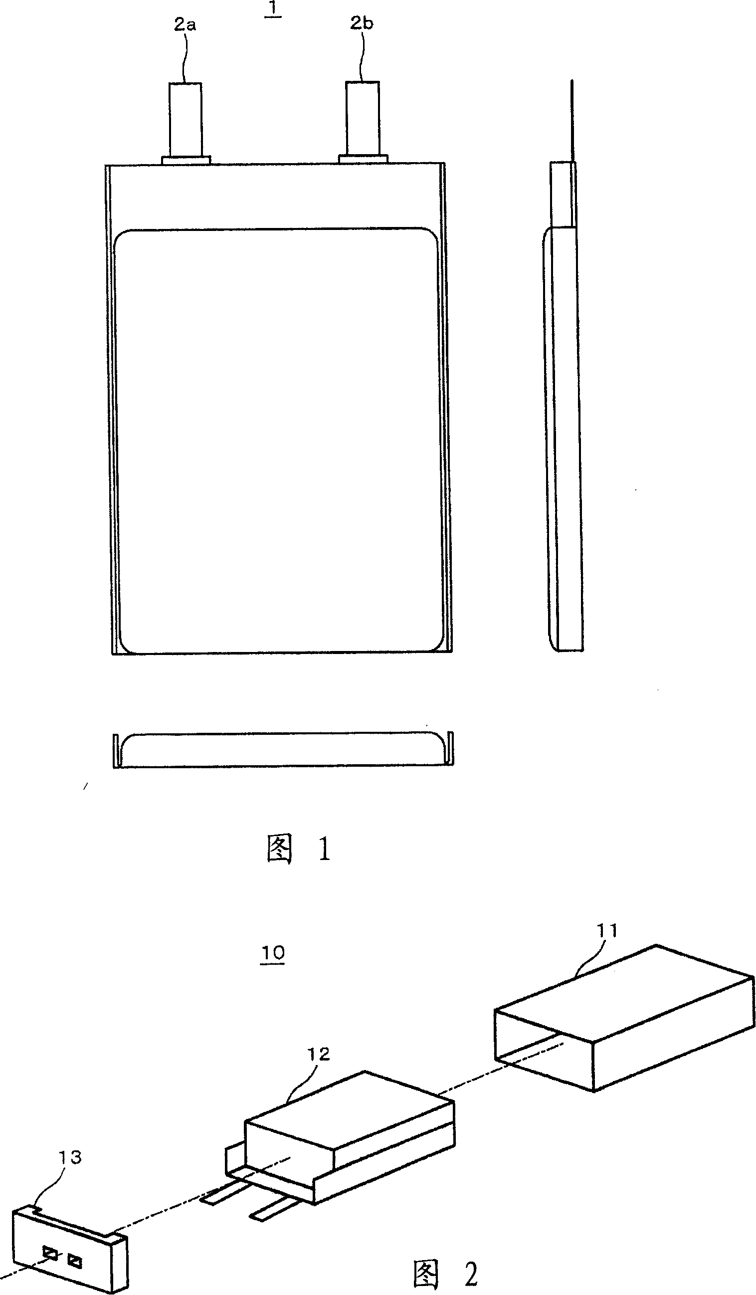
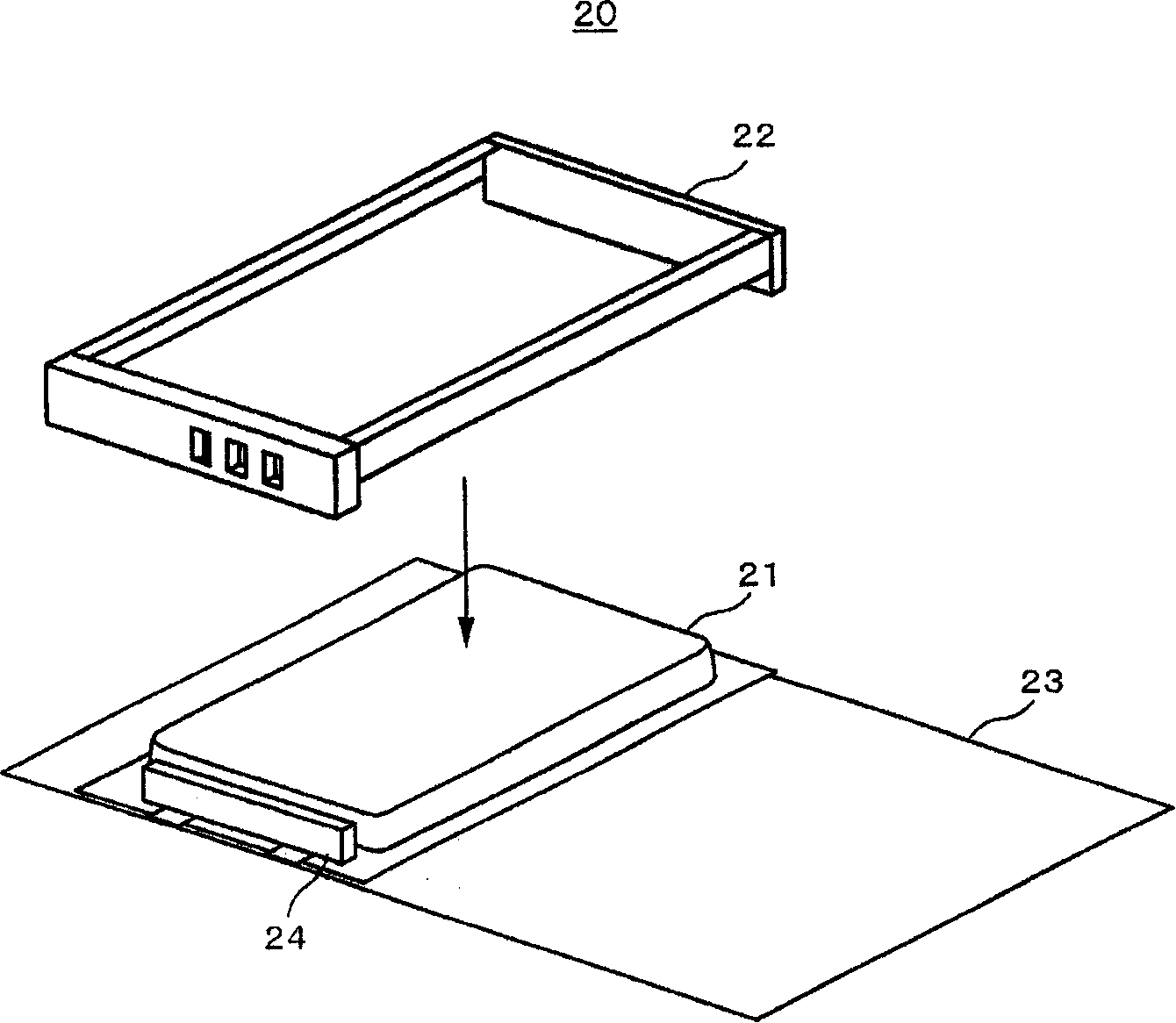
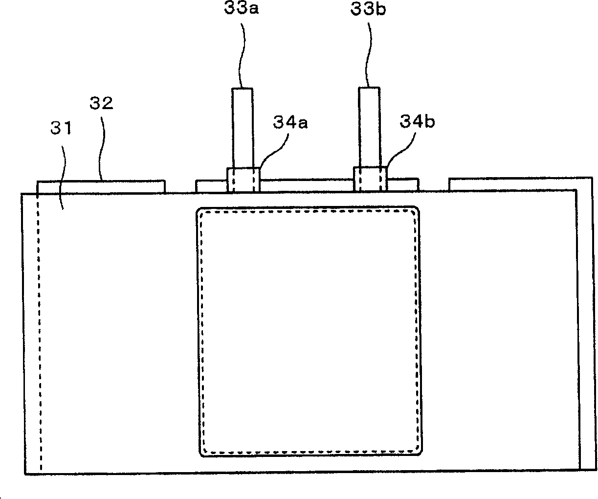
[0055] Figure 6 An appearance of a battery pack for a lithium ion polymer secondary battery according to an embodiment of the present invention is shown. The battery pack 40 includes an electrical generator device contained in a rigid laminate film 41 as a covering material, a top cover 42 and a bottom cover 43, and optionally a product label 46, wherein the top cover and the bottom cover are resin molded covers and assembled into the openings at the ends of the cover material.

[0056] In this description, a unit with a battery element covered by a flexible laminate film is referred to as a "generator device", and a unit with a generator device covered by a rigid laminate film 41 is referred to as a "battery cell", with Such as Figure 6 The shown unit having the structure of the battery cell to which the ...

no. 2 approach

[0132] In a second embodiment, a battery pack using a rigid laminate film having a three-layer structure as a rigid covering material is described.

[0133] The packaging structure of the battery pack according to the second embodiment and Figure 6 The structure is similar to that of the first embodiment shown in 7. In addition, the battery element and the power generator device are similar to those in the first embodiment, so descriptions thereof are omitted.

[0134] Preparation of battery cells

[0135] The generator device 50 consists of Figure 22 The illustrated rigid laminate film 80 having a three-layer structure is overlaid to form a battery cell. First, the structure of the rigid laminate film 80 will be described.

[0136] Such as Figure 22 As shown, the rigid laminated film 80 in the second embodiment is composed of a multilayer film having moisture resistance and insulating properties, and the multilayer film includes a metal foil indicated by reference num...

Embodiment

[0150] Hereinafter, the present invention will be described in detail with reference to the following examples, but these examples are not intended to limit the scope of the present invention.

[0151] (I) thermal adhesion test

[0152] Using a rigid laminate film having a three-layer or four-layer structure prepared using different resin materials in the sealant layer and the thermal adhesive layer, the measurements of the following items (a) to (c) were individually performed.

[0153] Rigid laminate films in Examples 1-1 to 1-34 and Comparative Examples 1-1 and 1-2 were prepared separately, wherein Al was used for the metal layer and Ny was used for the outer packaging layer, Table 1 below The materials shown in were used for the sealant layer and thermal bond layer. The outer wrapping layer and the sealant layer are separately formed by applying a film material to the metal foil via an adhesive layer, and the thermal adhesive layer is formed by diluting a hot-melt resin w...


PUM

PropertyMeasurementUnit
thicknessaaaaaaaaaa
thicknessaaaaaaaaaa
thicknessaaaaaaaaaa

Abstract

A battery pack is provided. The battery pack includes: a generator device having a battery element disposed on a flexible covering material folded to cover the battery element, wherein three sides of the flexible covering material around the battery element are sealed; a rigid covering material for covering the generator device, having an opening and being bonded to the flexible covering material of the generator device; and a cover fitted into the opening of the rigid covering material, wherein the rigid covering material has a three-layer structure having an outer packaging layer, a metal layer, and a heat-bonding layer which are stacked on one another, and the heat-bonding layer is one selected from an ethylene-vinyl acetate copolymer, an ethylene-acrylic acid copolymer, an ethyl acrylate copolymer, a methyl acrylate copolymer, a methacrylic acid copolymer, a methyl methacrylate copolymer, polyacrylonitrile, an ethylene vinyl alcohol resin, a polyamide resin, a polyester resin, acid-modified polypropylene, or an ionomer.

Description

field of invention [0001] The present invention relates to battery packs applied to, for example, lithium ion secondary batteries. Background technique [0002] In recent years, various portable electronic devices such as video tape recorders (VTRs) with cameras, cellular phones, and laptop computers are widely used, and devices with smaller size and weight are being developed. As portable electronic devices are miniaturized, the requirements for batteries as their power sources are also rapidly increasing, and in order to reduce the size and weight of the devices, the batteries of these devices must be designed so that the weight of the battery is light, thin and the Space can be used efficiently. As a battery that can satisfy these requirements, a lithium ion secondary battery having a large energy density and a high power density is most preferable. [0003] In particular, batteries with high shape selectivity, sheet-type batteries with reduced thickness and large area,...

Claims


Application Information

Patent Timeline
Patent Type & Authority Applications(China)
IPC IPC(8): H01M2/02H01M2/10H01M50/119H01M50/121H01M50/129H01M50/136H01M50/186H01M50/193H01M50/55H01M50/553H01M50/574
CPCY02E60/12H01M2/0404H01M10/0525H01M10/0431H01M2/021H01M2/34H01M2/08H01M10/0436H01M2/0287H01M2200/106H01M2/0275Y02E60/10H01M50/124H01M50/553H01M50/121H01M50/55H01M50/186H01M50/193H01M50/129H01M50/136H01M50/574H01M50/119H01M50/572H01M50/20H01M10/42
Inventor 八田一人佐藤雅人杉山毅山田弘幸坂井亨次间间田纪雄山本鑑本田一良
Owner MURATA MFG CO LTD
Why Eureka
Try Eureka