
Near-infrared spectrometer

A near-infrared spectrometer and near-infrared light technology, which is applied in the field of near-infrared spectrometers and can solve problems such as difficulty in use, complex structure, and reduced instrument analysis accuracy.

Inactive Publication Date: 2008-06-18
CHINA JILIANG UNIV
View PDF0 Cites 27 Cited by
  • Summary
  • Abstract
  • Description
  • Claims
  • Application Information

AI Technical Summary

Problems solved by technology

[0003] The several filters equipped with traditional filter-type near-infrared spectrometers are all tailored by the instrument developers according to the user's application occasions. The characteristic wavelengths used to analyze a certain component of a certain sample have been completed in the instrument development stage. If the actual sample or composition to be analyzed is changed relative to the development purpose of the instrument, even if it is re-calibrated, the analytical accuracy of the instrument will generally decrease significantly, and its application is limited to a certain extent
With the development of near-infrared spectroscopy instrument technology, chemometric methods based on continuous wavelengths, such as PCR (Principal Component Regression), PLSR (Partial Least Squares Regression), ANN (Artificial Neural Network), etc., represent the modern near-infrared spectroscopy technology. The development direction of the corresponding continuous wavelength instrument has strong versatility and stable performance, but the structure is relatively complex and expensive
The method of regression modeling using the above chemometric method is difficult to use on traditional discrete wavelength spectrometers, which seriously hinders the further development of discrete wavelength near-infrared spectrometers

Method used


Image

  • Near-infrared spectrometer
  • Near-infrared spectrometer

Examples


Embodiment Construction

[0014] The present invention will be further described below in conjunction with the accompanying drawings, and specific implementation methods will be given.

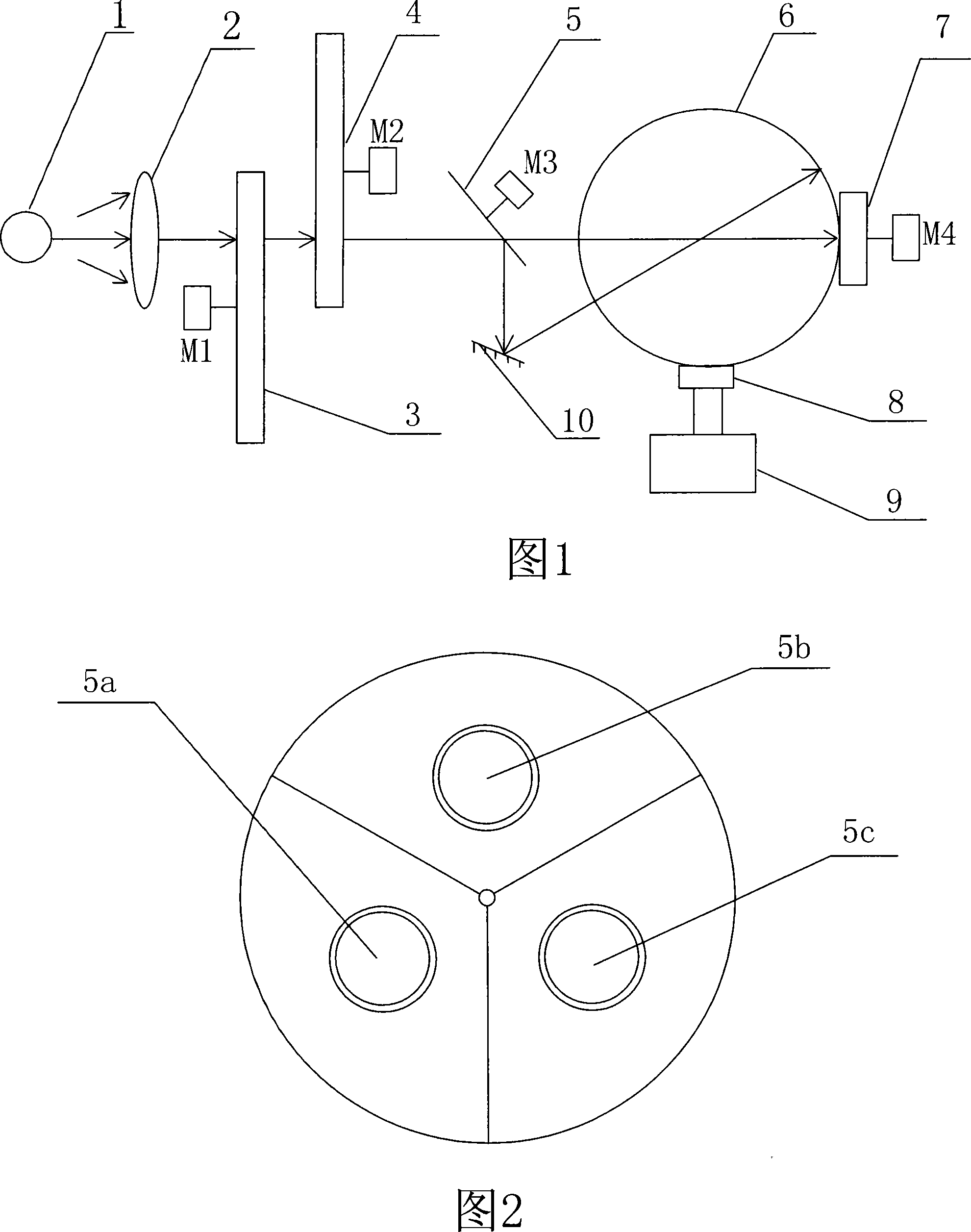
[0015] The near-infrared light source 1 adopts a halogen tungsten lamp, and the near-infrared light source 1 and the collimating lens 2 form a light source system, and the rear position of the collimating lens 2 is set by the motor M 1 Driven by the light intensity control disc 3 and by the motor M 2 The front and rear positions of the driven optical filter disc 4, light intensity control disc 3 and optical filter disc 4 can be interchanged. Wherein the light intensity control disc 3 is equipped with 10 fan-shaped holes on the circumference of the same circle center as the light intensity control disc 3, and the light passing width and light blocking width of the holes match the light passing diameter of the optical filter to ensure that the light intensity can Completely passing and completely blocking, 20 filters wi...


PUM


Abstract

The invention provides a near-infrared spectrograph, which belongs to the technical field of photoelectric test. The invention is characterized in that a near infrared light source and a collimating lens are matched up to constitute an illuminant system. The back position of the collimating lens is suitably provided with a light intensity modulation disc and an optical filter, and then is suitably provided with a dual-light path changer consisting of a dual-light path episcotister and a reflector. The dual-light path changer is connected with an integrating sphere light path arranged on the front part. A rotary sample cell and a photodetector connected with a signal processor are suitably arranged on an integrating sphere. The invention has simple structure, and the cost is low. Like a continuous wavelength type spectrograph when used, the invention makes use of a scaling method based on continuous spectrum to analyze a special ingredient, and the characteristic wavelength of the instrument does not need determining at the phase of research and development of the instrument. The invention makes use of the characteristics of large band width of the optical filter-type one, and the structures of the integrating sphere, the dual light paths, the rotary sample cell and so on to achieve the technical effects of a quasicontinuous wavelength type spectrograph, thus significantly improving the signal to noise ratio, the stability and the versatility.

Description

technical field [0001] The invention belongs to the technical field of photoelectric testing, and in particular relates to a near-infrared spectrometer. Background technique [0002] In near-infrared spectroscopy applications, spectral resolution is no longer an important indicator of instrument performance. At present, both computer simulation and experiment have proved that the spectral bandwidth of the instrument is 2nm, 10nm, 20nm does not affect the analysis results. More attention is paid to the signal-to-noise ratio and stability of the instrument, which is mainly manifested in the accuracy and stability of absorbance. [0003] The several filters equipped with traditional filter-type near-infrared spectrometers are all tailored by the instrument developers according to the user's application occasions. The characteristic wavelengths used to analyze a certain component of a certain sample have been completed in the instrument development stage. If the actual sample ...

Claims


Application Information

Patent Timeline
Patent Type & Authority Applications(China)
IPC IPC(8): G01N21/35G01N21/359
Inventor 金尚忠王动民袁琨陈华才朱周洪王焱华柴金朝
Owner CHINA JILIANG UNIV
Learn More