
Steam jet type heat pump heat distribution system for recovering thermal power plant condensing residual heat

A technology for heating systems and thermal power plants, applied in heating systems, hot water central heating systems, heating methods, etc., can solve problems such as waste, energy depreciation, and energy waste, and achieve simple equipment manufacturing, enhanced heat exchange effects, and full The effect of the heat transfer area

Inactive Publication Date: 2008-08-13
TSINGHUA UNIV
View PDF0 Cites 93 Cited by
  • Summary
  • Abstract
  • Description
  • Claims
  • Application Information

AI Technical Summary

Problems solved by technology

[0003] At present, the use of high-quality steam and low-quality steam in the steam heating system of cogeneration is still relatively common. Many medium-pressure steam produced by thermal power plants are vented or depressurized because they cannot be used in technology or public facilities, resulting in energy consumption. depreciation and waste
The power plant also produces a considerable amount of low-pressure steam in various production links, which is discarded. For example, in order to ensure the cooling of the low-pressure cylinder, a certain amount of steam must pass through the low-pressure cylinder to take away the heat generated by the friction loss caused by the blast. , the heat in the condensed steam of this part of the steam turbine accounts for more than 15% of the total input energy of the combined heat and power unit, and is generally discharged to the environment directly through the cooling tower through the circulating cooling water, thus causing huge energy waste

Method used


Image

  • Steam jet type heat pump heat distribution system for recovering thermal power plant condensing residual heat
  • Steam jet type heat pump heat distribution system for recovering thermal power plant condensing residual heat

Examples


Embodiment Construction

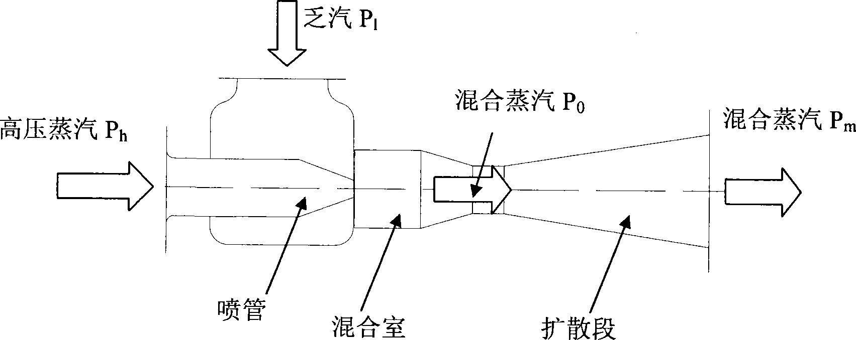
[0023] See attached figure 1 , figure 1 It is a schematic structural diagram of a typical single-stage steam ejector, based on the working principle of the ejector: working steam (pressure P h Higher pressure steam) accelerates through the nozzle in the injector to form a high-speed or even supersonic jet, while the ejected fluid (pressure P 1 The exhaust steam of the low-pressure steam turbine) is entrained by the high-speed jet into the mixing chamber, where the speed equalization and momentum (heat) transfer are carried out, and at the same time, accompanied by the increase of pressure, a single uniform mixed steam (pressure is P 0 medium pressure steam, P 1 0 k ). The mixed steam comes out of the mixing chamber and enters the diffusion section, and the pressure will continue to rise to P m (P 1 0 m k ). At the outlet of the diffuser section, the pressure P of the mixed steam m Higher than the pressure P of the ejected steam entering the mixing chamber 1 , so that ...


PUM


Abstract

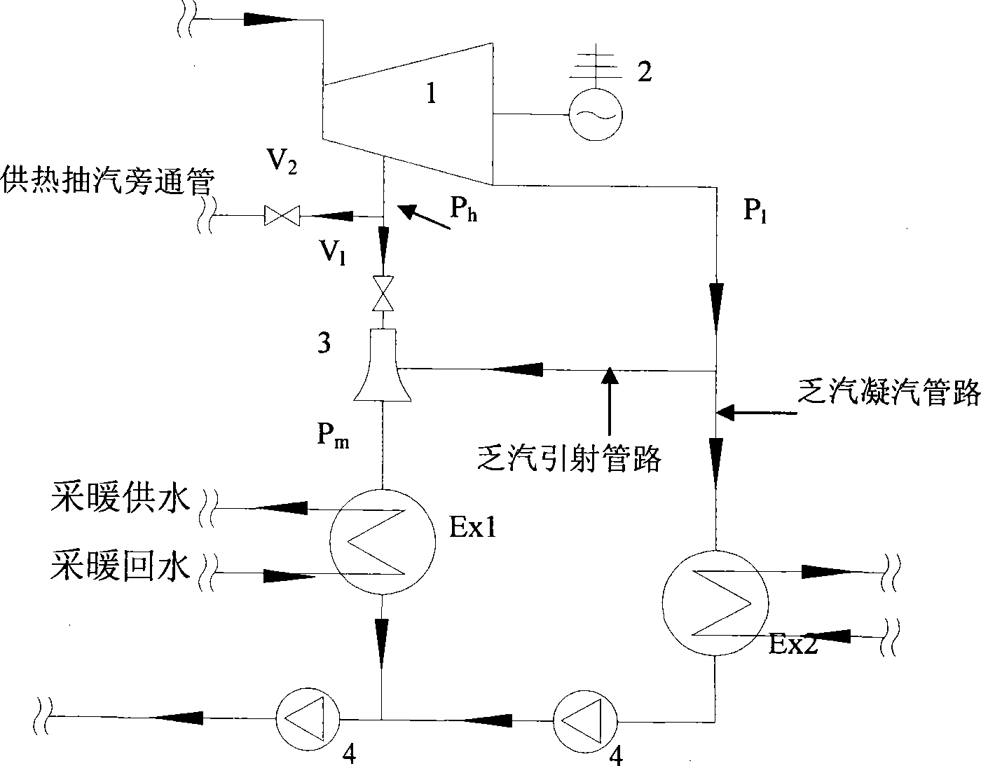
The present invention provides a steam injection heatpump heating system. The technical solution is that the system is composed of a steam injector, a high voltage steam pipeline, a low voltage steam pipeline, a throttling gear and a bypass connecting pipe. The high voltage steam enters in the heat exchanger heaing backwater after injecting lower steam turbine voltage condensing in low temperature, this realises waste heat recovery in low temperature condensing steam of the steam turbine. The core component is the steam injector, the high voltage heat supplying pumping is used as high-velocity jet acceleratively formed in the injecting tube of the working steam, and lower voltage steam turbine is rolled in the mixing room as injected flow, mixing steam in the expanding section of the steam injector is decelerately compressed in a certain back pressure, then sending to the heat interchanger for heating backwater, a certian back pressure mixing steam condenses to water after heat releasing in the exchanger, returning to the backwater system of electrical factory, completing thermal circuit of the combined heat and power generation set.

Description

technical field [0001] The invention belongs to the field of heat pump heat supply systems for recovering condensate waste heat of steam extraction and heat supply units in thermal power plants, in particular to a steam injection heat pump heat supply system capable of recovering condensate waste heat of thermal power plants that can use high-pressure heating steam to extract steam turbine condensate through ejectors system. Background technique [0002] In recent years, with the maturity and development of heat pump technology, various heat pump heating technologies have been widely promoted and applied in our country. A heat pump is a device that uses high-level energy to make a low-level heat source flow to a high-level heat source. The heat supplied by the heat pump (that is, the heat obtained by a high-level heat source) is the sum of the consumed high-level energy and the heat absorbed from a low-level heat source. Therefore, the use of a heat pump device can Make ful...

Claims


Application Information

Patent Timeline
Patent Type & Authority Applications(China)
IPC IPC(8): F24D3/18F22D11/06
CPCY02B30/12Y02P80/10
Inventor 付林张世钢胡鹏江亿
Owner TSINGHUA UNIV
Learn More