Method for converting methyl hydride into methyl hydride chloride

A methane chloride, methane technology, applied in chemical instruments and methods, organic chemistry, halogenated hydrocarbon preparation, etc., to achieve the effects of low operating cost, reasonable and simple process structure, and easy operation and use

Inactive Publication Date: 2008-08-20
黄立维
View PDF0 Cites 12 Cited by
  • Summary
  • Abstract
  • Description
  • Claims
  • Application Information

AI Technical Summary

Problems solved by technology

[0006] The problem to be solved by the present invention is to provide a new method for converting methane into methane chloride in view of the existing background technology. Using the method of discharge plasma chemical reaction, methane is converted into methane chloride, the basic chemical raw material. The process structure is reasonable and simple. Easy to operate and use, high processing efficiency

Method used


Image

  • Method for converting methyl hydride into methyl hydride chloride

Examples


Embodiment 1

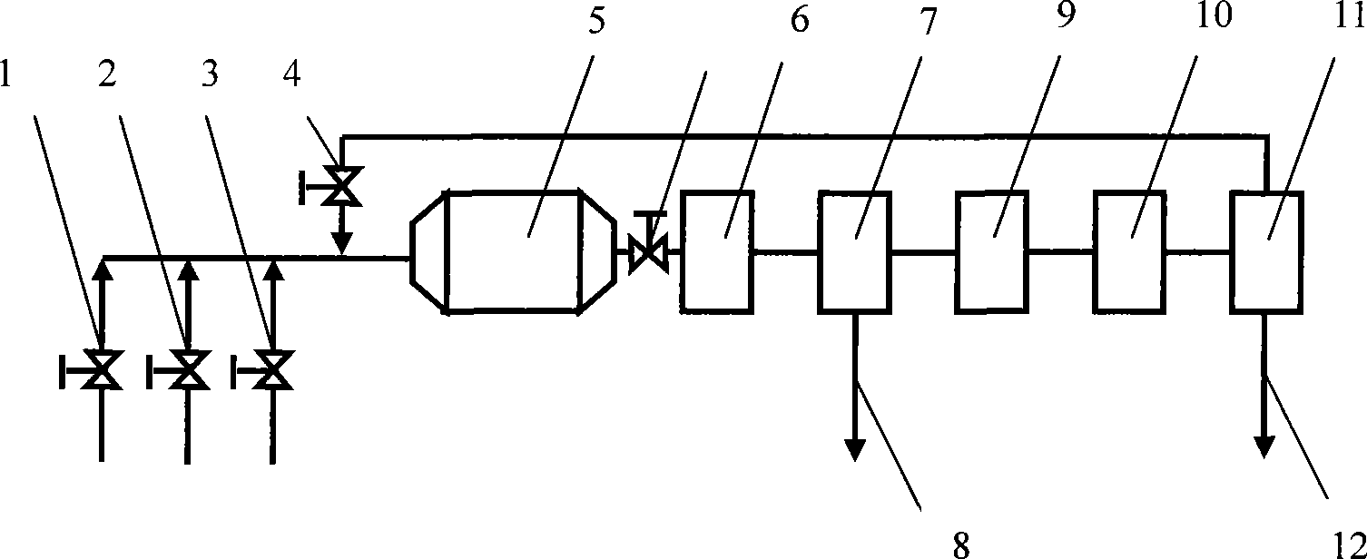
[0024] refer to figure 1 As shown in the process flow chart, the specific process flow is as follows: first replace the gas in the system with an inert gas to make the system pressure slightly higher than atmospheric pressure, then close the inert gas inlet valve 3, and open the methane feed gas inlet valve 1 and chlorine gas raw material gas inlet valve 2, so that methane and chlorine gas are introduced into the discharge plasma reactor 5 in a certain proportion, and power is supplied to the discharge plasma reactor. In the reactor, methane and chlorine gas generate free radicals under the action of the discharge plasma The reaction generates methane chloride, and then the reacted mixture is cooled to room temperature through the gas cooler 5, washed with water and absorbed, then added with dilute NaOH solution to absorb the secondary absorption dehydrochlorination tower 7 and calcium chloride dehydrator 9, and then passed through the gas pump 10 It is transported to the cond...

Embodiment 2

[0039] Concrete technological process is with embodiment 1, and condition parameter is as follows:

[0040] Gas composition: the inert gas is helium, and the inert gas accounts for 1% of the gas composition; raw material gas chlorine / methane=0.2, the temperature in the reactor is -34.5°C, the residence time of the reactor gas is 0.3s, and other conditions are the same as in Example 1 .

[0041] Product conversion rate is 3~5%, and each methane chloride composition (%) in the product:

[0042] Chloromethane 40~60;

[0043] Dichloromethane 20-40;

[0044] Chloroform 10-20;

[0045] Carbon tetrachloride 0-1.

Embodiment 3

[0047] Concrete technological process is with embodiment 1, and condition parameter is as follows:

[0048] Gas composition: the inert gas is neon, and the inert gas accounts for 95% of the gas component; the feed gas chlorine / methane=6, the temperature in the reactor is 80° C., the reactor gas residence time is 60 s, and other conditions are the same as in Example 1.

[0049] The product conversion rate is 85%, and each methane chloride composition (%) in the product:

[0050] Chloromethane 1~5;

[0051] Dichloromethane 5~15;

[0052] Chloroform 25-45;

[0053] Carbon tetrachloride 45~65.


PUM


Abstract

The invention discloses a method for transforming methane into methane chloride, which is characterized in that: gas with methane, chlorine and inert gas are introduced into discharge plasma reactors; methane is excited under the effect of discharge plasma in the reactor, and generates methane chloride by free radical reaction with chlorine; the obtained liquid product is the methane chloride after the reacted mixture is cooled, dehydrochlorinated, dried, dewatered, compressed and condensed gas-liquid, and separated, and the obtained gas returns the reactor and reacts again. The reaction of the invention can be done in normal temperature and pressure, and improves greatly energy utilization ratio, compared with the traditional methane chloride-heating technique processed in high temperature and pressure. Meanwhile, by adopting inert gas as the background gas of plasma chemical reaction, the reaction efficiency of the methane chloride is improved and increased; the inert gas can be used repeatedly; the whole technique is reasonable and simple in structure, easy in operation and application and low in moving cost.

Description

technical field [0001] The invention belongs to the field of gas discharge plasma chemical reaction and relates to a method for converting methane into methane chloride. Background technique [0002] Natural gas is regarded as one of the 21st century clean energy sources to replace coal burning. Methane burning has a much lower greenhouse effect on the planet than fossil fuels. At the same time, methane is the main component of biogas, a renewable resource, and a chemical raw material. Therefore, how to economically and rationally utilize abundant methane resources has been paid more and more attention. But many natural gas resources are in remote, sparsely populated areas, and their storage and methane levels vary and are expensive to transport over long distances. If the methane can be converted into liquid fuel or chemical raw material in situ, the transportation cost will be greatly reduced. From the perspective of resource utilization and environmental protection, m...

Claims


Application Information

Patent Timeline
Patent Type & Authority Applications(China)
IPC IPC(8): C07C19/01C07C17/10
Inventor 黄立维
Owner 黄立维
Why Eureka
Try Eureka