

Laser-double arc double sided compound welding method of T shaped joint
A hybrid welding and double arc technology, which is applied in laser welding equipment, arc welding equipment, welding equipment, etc., can solve the problems of small fusion diameter of lap joint surface, low weld shear strength and high cost, and increase the area of fusion surface , The effect of improving the energy utilization rate and increasing the welding speed
- Summary
- Abstract
- Description
- Claims
- Application Information
AI Technical Summary
Problems solved by technology
Method used
Image

Examples
specific Embodiment approach 1
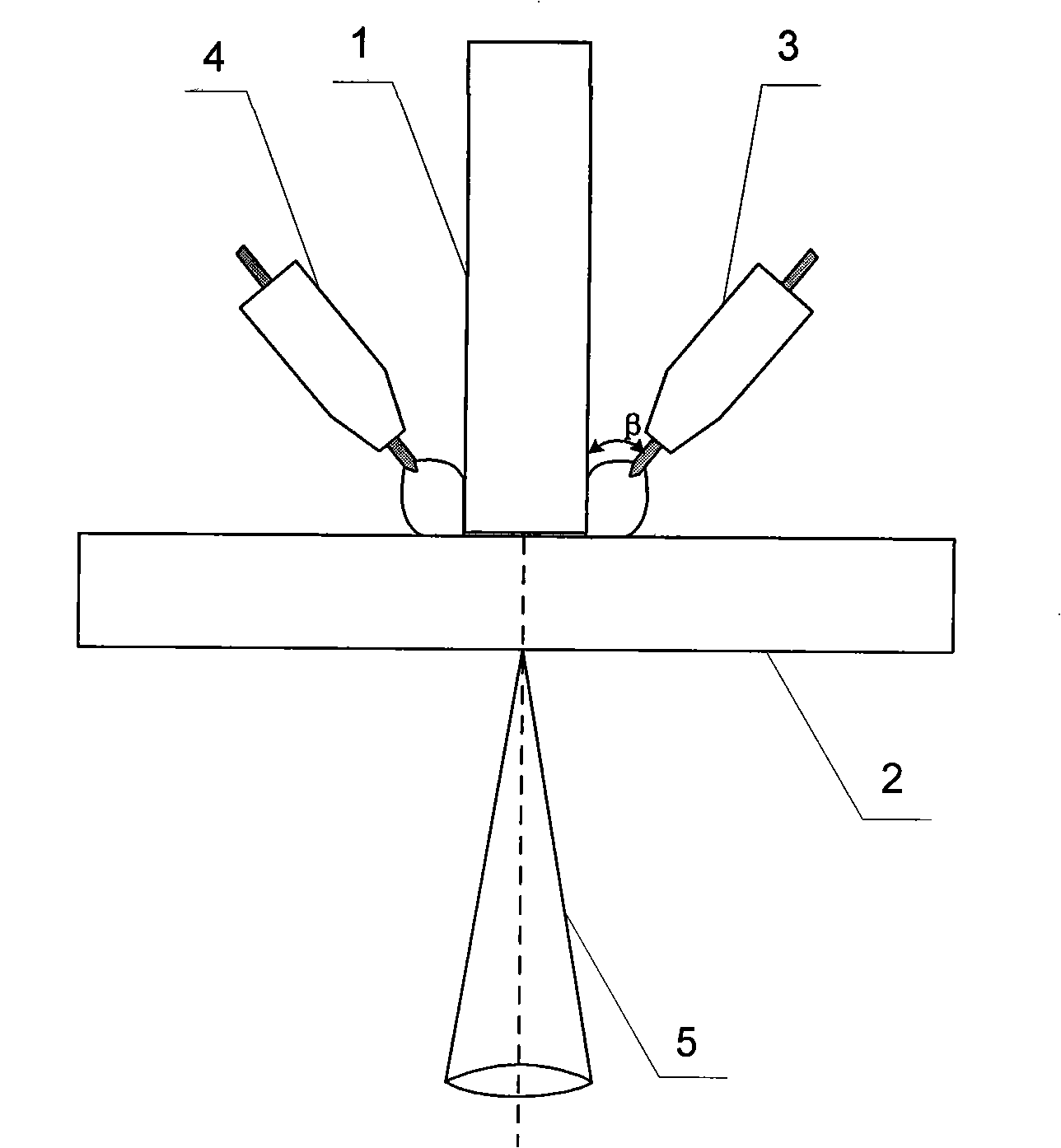
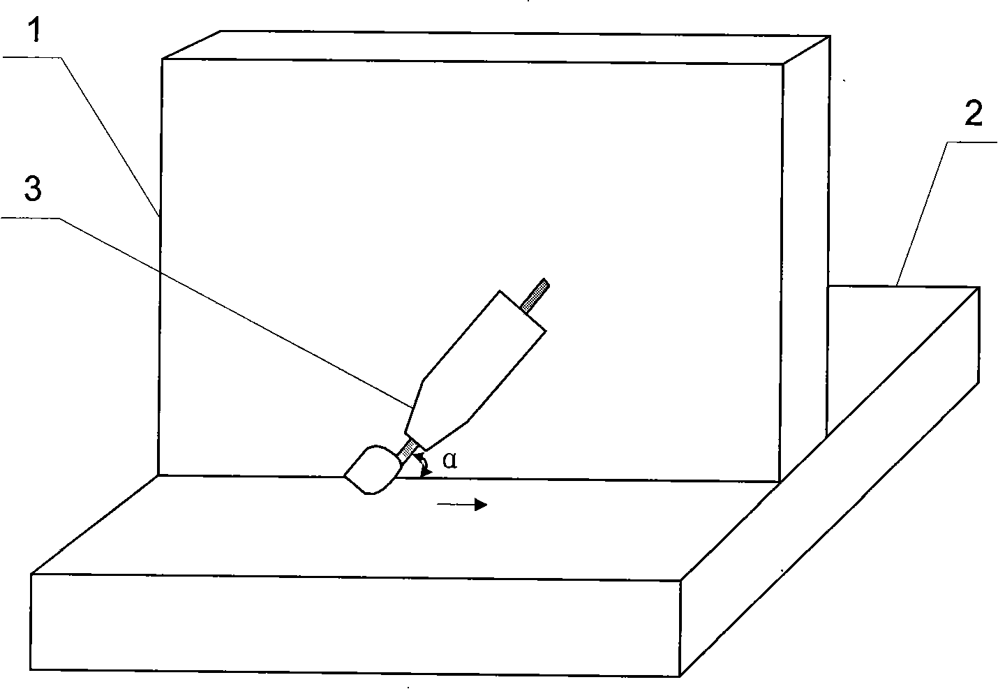
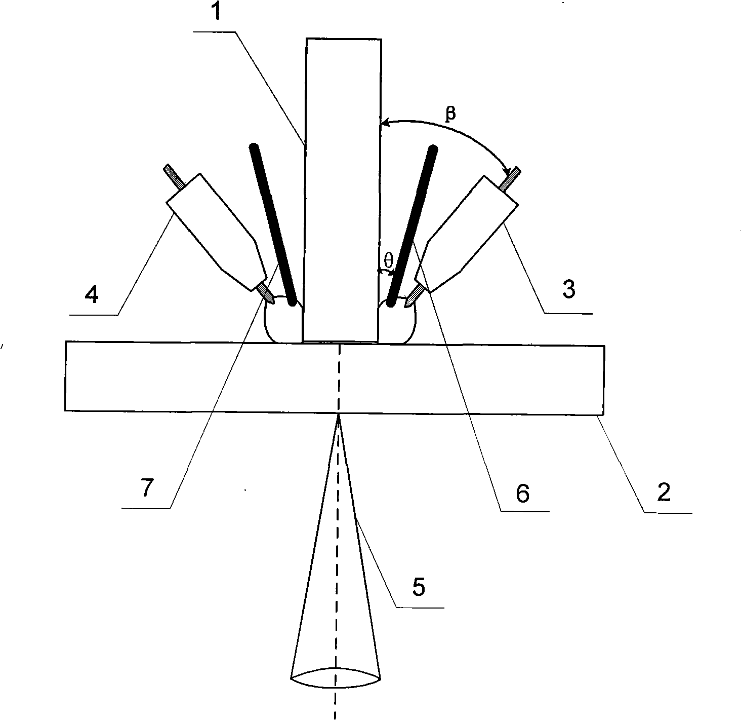
[0013] Specific implementation mode one: the following combination figure 1 , figure 2 Describe this embodiment, this embodiment adopts laser and double-arc double-sided composite welding for the workpiece to be welded of T-type joint, laser beam 5 forms the welding seam along the vertical plate 1 of T-type joint and the top plate 2 contacts from top plate 2 The top surface is vertically incident to perform penetration welding, while the first arc welding torch 3 and the second arc welding torch 4 perform welding synchronously with laser welding from both sides of the weld seam of the T-joint respectively, keeping the first arc welding torch 3 and the second arc welding torch 4 is placed symmetrically with respect to the vertical plate 1 left and right.
[0014] Welding effect comparison:
[0015] Figure 5 ~ Figure 7 The weld morphology of T-joint workpieces welded by different welding methods are shown respectively. When a single laser is used to perform penetration wel...
specific Embodiment approach 2
[0016] Embodiment 2: The difference between this embodiment and Embodiment 1 is that the type of laser beam 5 is CO 2 Gas laser beam, YAG solid-state laser beam, semiconductor laser beam or fiber laser beam, and others are the same as the first embodiment.
specific Embodiment approach 3
[0017] Embodiment 3: The difference between this embodiment and Embodiment 1 is that the welding method of the present invention is applicable to the connection of T-joint structures of the same material or dissimilar materials, and the others are the same as Embodiment 1.
PUM
| Property | Measurement | Unit |
|---|---|---|
| Diameter | aaaaa | aaaaa |
| Thickness | aaaaa | aaaaa |
| Thickness | aaaaa | aaaaa |
Abstract
Description
Claims
Application Information