Connection structure of aluminum electrolysis ceramic matrix inert anode and metal guide rod, and preparation thereof
An inert anode and connecting structure technology, which is applied in the field of preparation of the connecting structure, can solve the problems of easy corrosion failure of the connecting interface, poor electrical connection stability, easy falling off of the anode, etc., and achieves low curing shrinkage, good water and oil resistance, and low cost. low cost effect
- Summary
- Abstract
- Description
- Claims
- Application Information
AI Technical Summary
Problems solved by technology
Method used
Image

Examples
Embodiment 1
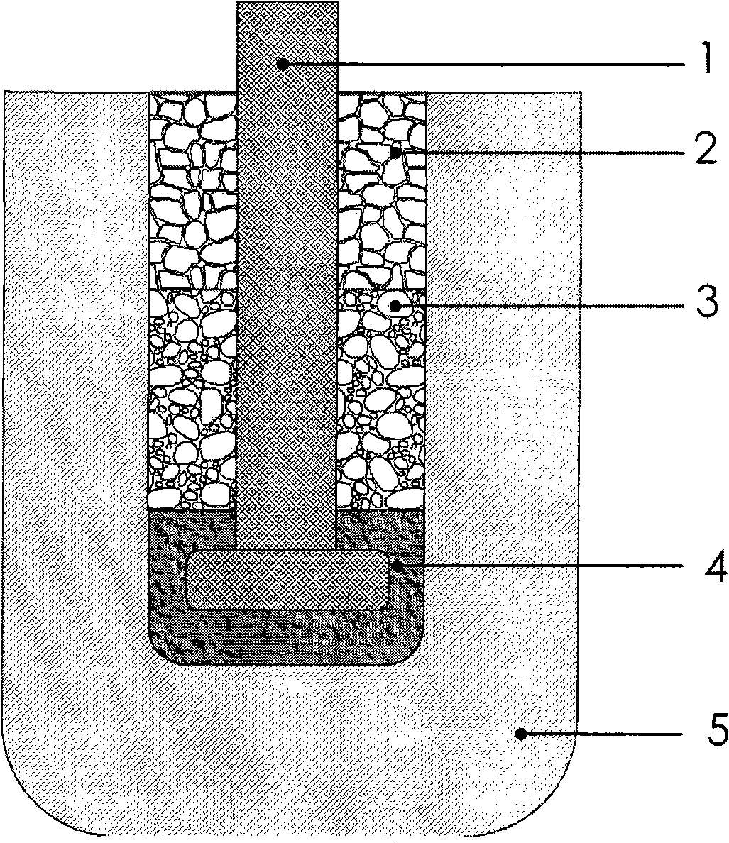
[0029] Such as figure 1 , depicting the schematic diagram of the connection process of the cup-shaped metal inert anode and the metal guide rod. It mainly includes a metal guide rod 1, a first binder 2, a second binder 3, a filling material 4, and a cup-shaped cermet inert anode 5. The composition is NiFe 2 o 4 -10NiO / 17Cu inert anode, conductive rod material is 1Cr18Ni9Ti or high temperature nickel-based alloy. The implementation process of the electrode bonding process is as follows: first, the inner surface of the cup-shaped inert anode 5 and the outer surface of the metal guide rod 1 are decontaminated and degreased, electroless nickel is plated, and the thickness of the coating is 120 μm; 2 o 4 + 25wt% copper powder + 25wt% Ni powder is placed at the bottom of the anode cup, and at the same time, the trapezoidal head of the metal guide rod 1 is partially embedded in the filler to form a filler 4 structure; the composition is 45wt% NiFe 2 o 4 The powder filler of +4...
Embodiment 2
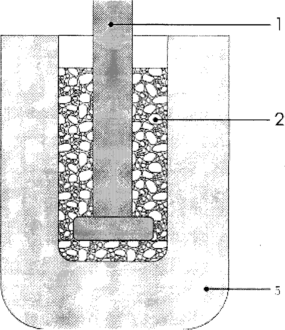
[0031] Such as figure 2 , depicting the schematic diagram of the connection process of the cup-shaped metal inert anode and the metal guide rod. It mainly includes a metal guide rod 1, a first binder 2, and a cup-shaped cermet inert anode 5. The composition is NiFe 2 o 4 -10NiO / 17Ni inert anode, conductive rod material is 1Cr18Ni9Ti or high temperature nickel-based alloy. The implementation process of the electrode bonding process is as follows: first, the inner surface of the cup-shaped cermet inert anode 5 and the outer surface of the metal guide rod 1 are decontaminated and degreased, electroless silver plating is performed, and the thickness of the coating is 20 μm; the composition is 35wt%NiFe 2 o 4 +45wt% silver-copper alloy powder+15wt% CuO+5wt% ZrO 2 Mix the powder filling material with a solid-to-liquid ratio of 0.6 and a phosphate solution with a mass concentration of 70%, and then fill it into the anode cup to form a binder 2, and at the same time, partially e...
Embodiment 3
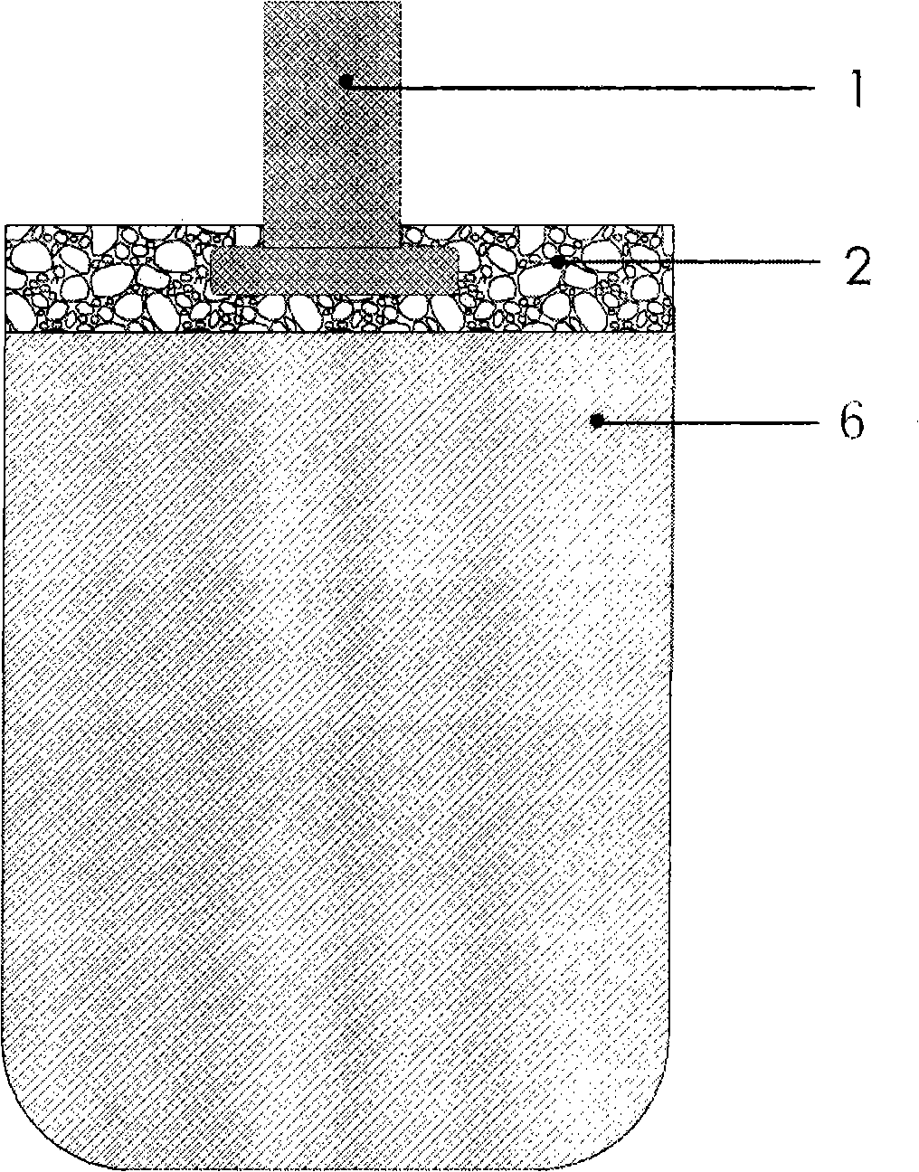
[0033] image 3 It is a schematic diagram of a cylindrical or square inert anode connection process, mainly including a metal guide rod 1, a first binder 2, and a cylindrical or square inert anode 6. The composition is NiFe 2 o 4 -10NiO / 17Cu inert anode, conductive rod material is Cr18Ni9Ti. The implementation process of the bonding process of the electrode is as follows: first, the outer surface of the cylindrical or square inert anode 6 and the metal guide rod 1 is decontaminated and degreased, and the surface to be connected of the cylindrical or square inert anode 6 and the outer surface of the metal guide rod 1 The surface is electroplated with copper, the thickness of the coating is 200 μm, and then the composition is 45wt% NiFe 2 o 4 +40wt%Cu+5wt%Ag+10wt%CuO powder filler is injected into a phosphate solution with a solid-to-liquid ratio of 0.3 and a mass concentration of 60%. After uniform mixing, it is coated on the surface of the anode to be connected, and then t...
PUM
| Property | Measurement | Unit |
|---|---|---|
| thickness | aaaaa | aaaaa |
| thickness | aaaaa | aaaaa |
Abstract
Description
Claims
Application Information
 - R&D
- Intellectual Property
- Life Sciences
- Materials
- Tech Scout
- Unparalleled Data Quality
- Higher Quality Content
- 60% Fewer Hallucinations
Browse by: Latest US Patents, China's latest patents, Technical Efficacy Thesaurus, Application Domain, Technology Topic, Popular Technical Reports.
© 2025 PatSnap. All rights reserved.Legal|Privacy policy|Modern Slavery Act Transparency Statement|Sitemap|About US| Contact US: help@patsnap.com