Color filter, process for producing the same, and liquid crystal display device

A manufacturing method and color filter technology, applied in the field of color filters, can solve problems such as narrowing of the effective range and insufficient sensitivity, and achieve the effect of expanding the effective range of development

Inactive Publication Date: 2009-01-14
FUJIFILM CORP
View PDF62 Cites 5 Cited by
  • Summary
  • Abstract
  • Description
  • Claims
  • Application Information

AI Technical Summary

Problems solved by technology

However, in the resin composition using the carbon black, for example, laser light (for example, wavelength 405 nm) used in maskless exposure is absorbed, so there is insufficient sensitivity and the effective latitude of development (latitude) becomes narrow. The problem
Especially, when the density or height of the black matrix is ​​increased, this problem becomes remarkable

Method used

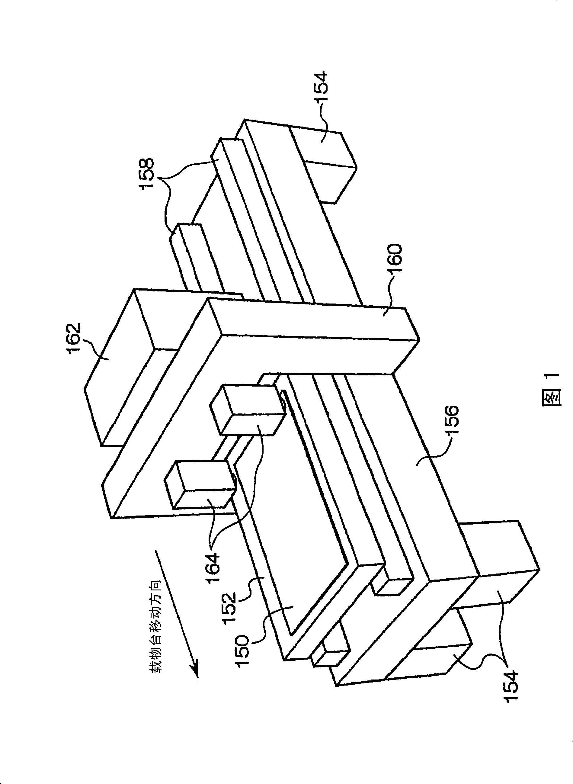
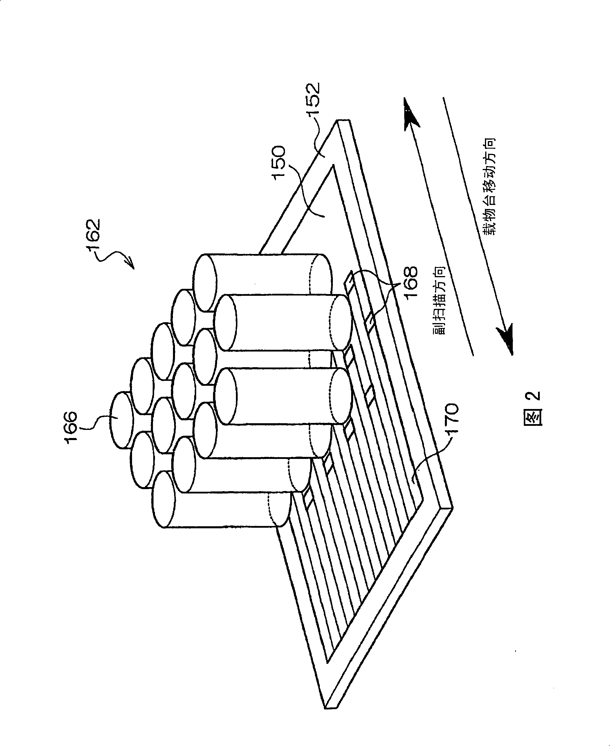
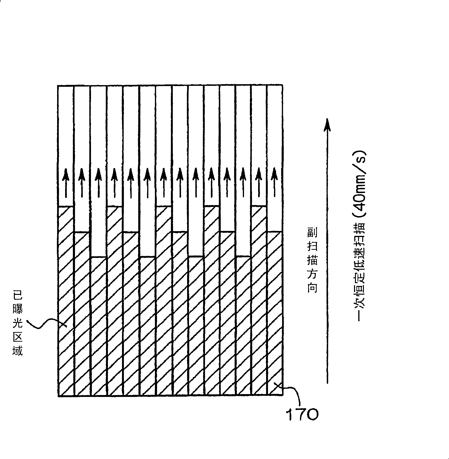

Image

  • Color filter, process for producing the same, and liquid crystal display device
  • Color filter, process for producing the same, and liquid crystal display device
  • Color filter, process for producing the same, and liquid crystal display device

Examples


Embodiment 1

[0318] (Example 1): coating method

[0319]

[0320] Dissolve 23.1 g of silver (I) acetate, 65.1 g of tin acetate, 54 g of gluconic acid, 45 g of sodium pyrophosphate, 2 g of polyethylene glycol (molecular weight 3000), and E735 (manufactured by ISP, vinylpyrrolidone / vinyl acetate copolymer) 5 g to obtain solution 1.

[0321] Separately, 36.1 g of hydroxyacetone was dissolved in 500 ml of pure water to obtain a solution 2.

[0322] While keeping the solution 1 obtained above at 25° C., while vigorously stirring, the above solution 2 was added thereto within 2 minutes, and stirring was continued slowly for 6 hours. In this way, the mixed liquid changed to black, and silver-tin composite particles were obtained. Then, the liquid was centrifuged to precipitate silver-tin composite particles. The centrifugation was divided into a small amount of 150 ml liquid, and it was carried out for 30 minutes at a rotation speed of 2000 r.p.m using a desktop centrifugal separator H-103n...

Embodiment 2

[0413] The color filter was formed by the method similar to Example 1 except having changed the formulation of the photosensitive resin composition 2 described in said Table 1.

Embodiment 3

[0415]

[0416] Mixed silver particles (major axis length L: 400nm, width b: 30nm, thickness t: 25nm, b / t=1.2) 73.5g, Solspa (Solspa) 20000 (manufactured by Abyssia; dispersion agent) 1.05g, and methyl ethyl ketone 16.4g. This was dispersed using an ultrasonic dispersant (Ultrasonic generator model US-6000ccvp, manufactured by Nissei Co., Ltd.) to obtain a silver microparticle dispersion liquid having a circle-equivalent diameter of 100 nm.

[0417]

[0418] The following compositions were mixed to prepare a photosensitive resin composition.

[0419] 〔composition〕

[0420] ·Silver particle dispersion ...26.1 parts

[0421] ·Propylene glycol monomethyl ether acetate ...28.6 parts

[0422] ·Butanone ...37.6 parts

[0423] 1...0.21 parts of the surfactant

[0424] ·Hydroquinone monomethyl ether ...0.001 parts

[0425]· Benzyl methacrylate / methacrylic acid copolymer ... 2.18 parts

[0426] (Molar ratio=73 / 27, molecular weight 30000)

[0427] Bis[4-[N-[4-(4,6-bistrichlo...


PUM

PropertyMeasurementUnit
Sizeaaaaaaaaaa
Film thicknessaaaaaaaaaa

Abstract

This invention provides a process for producing a color filter, a color filter produced by this production process, and a liquid crystal display device using the color filter. The process for producing the color filter is characterized by comprising the step of relatively scanning a layer of a photosensitive resin composition containing at least one of a resin and its precursor, and at least one of particles of a metal or an alloy and composite particles of a metal and an alloy or composite particles of an alloy and an alloy, using two-dimensionally arranged spatial light modulation device, while modulating light based on image data to form a two-dimensional image by exposure and thus to form deep color pixel walls.

Description

technical field [0001] The present invention relates to a liquid crystal display device used in a small mobile device, a large display, etc., a color filter used in the liquid crystal display device, and a manufacturing method thereof. Background technique [0002] A liquid crystal display device or an organic EL display device is very compact, and has performance equal to or higher than that of a conventional CRT display, which is the mainstream, and thus has been replacing the CRT display in recent years. [0003] The color image displayed by such a display device is formed as follows: the light passing through the substrate composed of color filters composed of multiple colors is directly colored by each color constituting the color filter, and the colored light of a plurality of colors is synthesized Formed for what the image looks like. Also, currently, a color image is formed by using pixels of three colors of red (R), green (G), and blue (B) constituting a color filt...

Claims


Application Information

Patent Timeline
IPC IPC(8): G02B5/20G02F1/1335
CPCG02B5/201G02B5/206B29D11/00634B41J2202/09G02F1/133516
Inventor 大谷薰明畠山晶
Owner FUJIFILM CORP
Why Eureka
Try Eureka