Deposition technique of arc ion plating enhanced by magnetic field
A technology of arc ion plating and deposition process, which is applied in the direction of ion implantation plating, metal material coating process, sputtering plating, etc., which can solve the inhomogeneity of plasma transmission space distribution and affect the performance of coating and film and life, limiting the application range of arc ions, etc., to achieve the effect of improving the transmission space distribution, increasing the utilization rate of the target material, and improving the uniformity of deposition
- Summary
- Abstract
- Description
- Claims
- Application Information
AI Technical Summary
Problems solved by technology
Method used
Image
Examples
Embodiment 1
[0045] Example 1: Improved Traditional Deposition Process
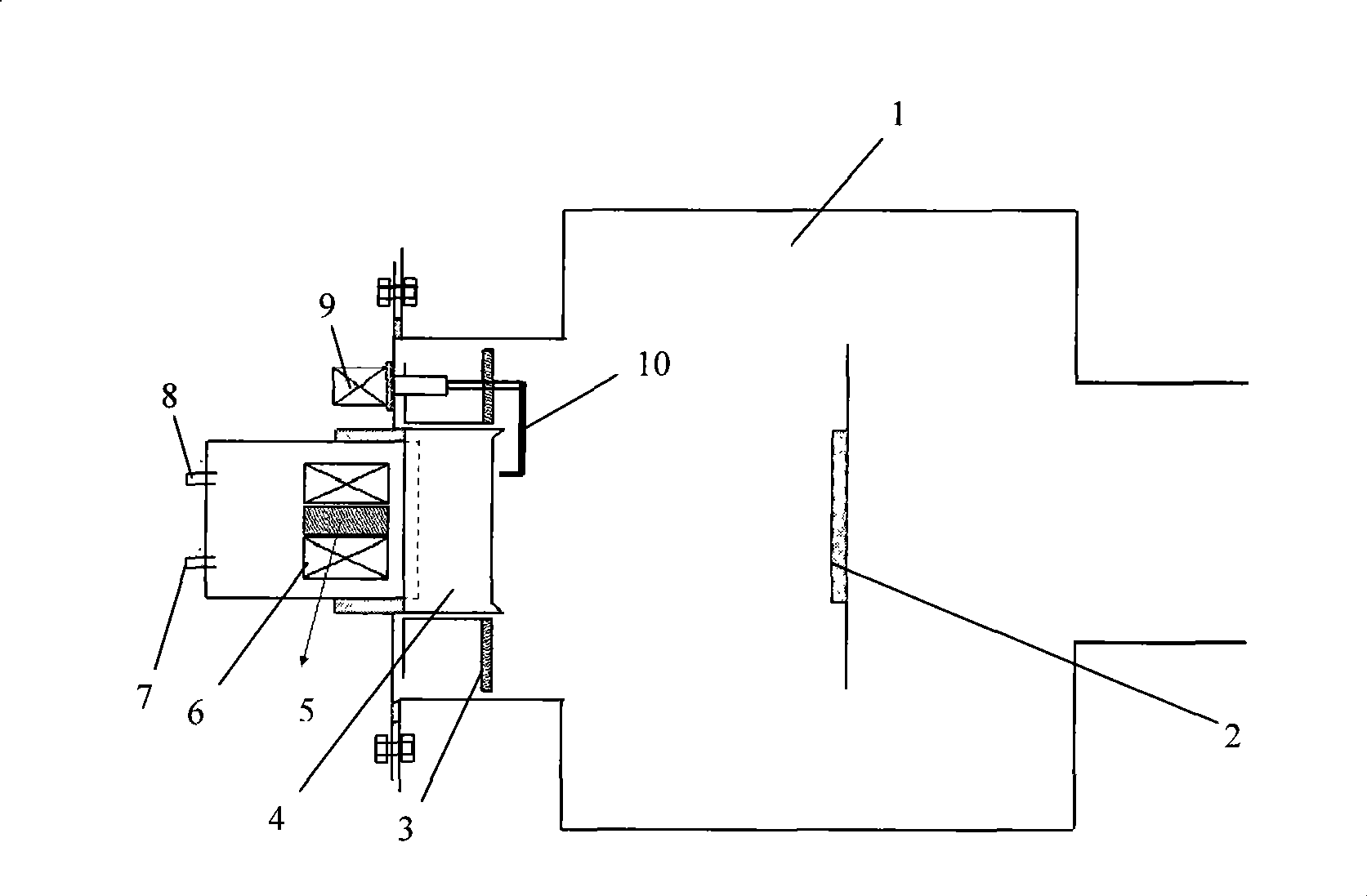
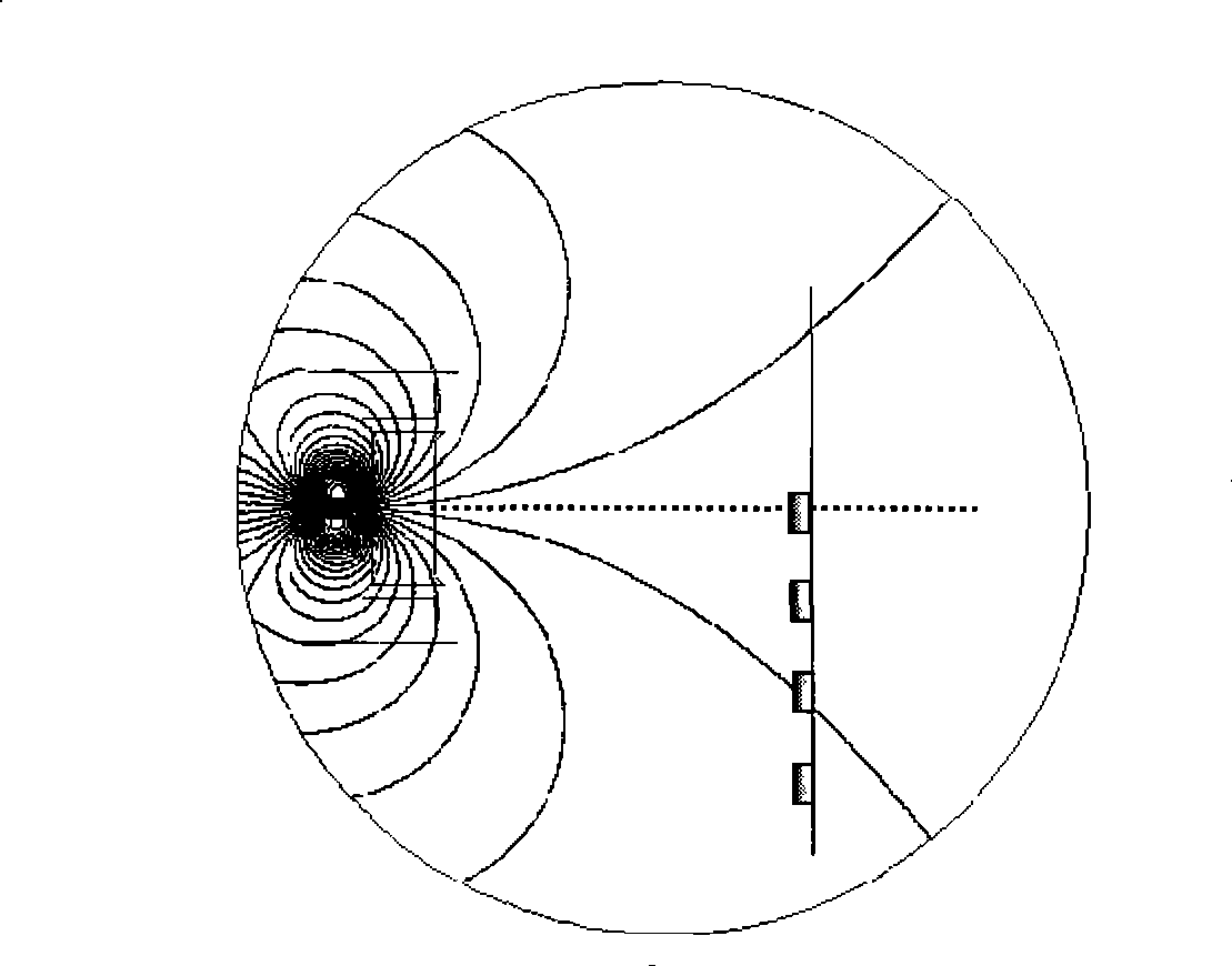
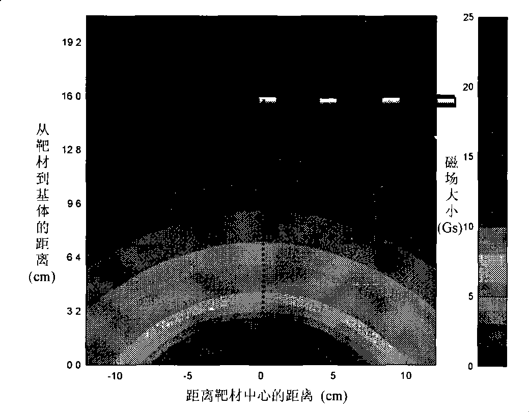
[0046] The method of simply applying a magnetic field near the target surface is used to control the movement of the arc spot on the target surface, see appendix figure 1 , The arc ion plating deposition device mainly includes a vacuum chamber 1, a substrate (sample) 2, a magnetic ring 3, a target material 4, nickel-plated pure iron 5, an electromagnetic coil 6, an inlet pipe 7, an outlet pipe 8, and an arc coil 9. Arc starting needle 10, etc., set substrate (sample) 2, magnetic ring 3, target 4, arc starting needle 10 in vacuum chamber 1, the front of target 4 is opposite to substrate (sample) 2, target 4 Electromagnetic coil 6 is arranged on the back, and nickel-plated pure iron 5 is installed in the middle of electromagnetic coil 6. The circulating water circulates through water inlet pipe 7 and outlet pipe 8 to cool target material 4. Nickel-plated pure iron 5 and electromagnetic coil 6 are installed on Inside th...
Embodiment 2
[0049] The difference from Example 1 is that a new magnetic field enhancement process is adopted, consisting of two sets of magnetic field generating devices, one set is placed behind the target, and the magnetic field generating device is the same as that in Embodiment 1, that is, it is installed in the middle of the electromagnetic coil 6 Nickel-plated pure iron 5 is mainly used to control the movement of the arc spot. Another set of magnetic field enhancement coils 11 is placed on the back of the substrate (sample) 2 in the vacuum chamber 1. It consists of a coil and is mainly used to restrict the transmission of plasma. , improve the transmission efficiency and the ion density near the substrate, improve the uniformity of ion distribution near the substrate, and achieve the purpose of increasing the film deposition rate and deposition uniformity. The sample is placed near the front of the coil, see attached Figure 4 .
[0050] The electromagnetic coil placed in the vacuu...
Embodiment 3
[0053] The difference from Example 1 is that a new magnetic field enhancement process is adopted, consisting of two sets of magnetic field generating devices, one set is placed behind the target, and the magnetic field generating device is the same as that in Embodiment 1, that is, it is installed in the middle of the electromagnetic coil 6 Nickel-plated pure iron 5, another set of magnetic field generating device (magnetic field enhancing coil 11) is the same as that in Embodiment 2, and the process of magnetic field configuration and adjustment is also the same. The difference is that the magnetic field enhancement coil 11 is placed in front of the substrate (sample) 2 in the vacuum chamber 1, see appendix Figure 7 ,8. The effect of placing the sample behind the coil is different from that of Example 2, because the trajectory of the charged particles is different due to the difference in the configuration of the magnetic field near the sample, and the structural properties ...
PUM
 Abstract
Description
Claims
Application Information
 - R&D
- Intellectual Property
- Life Sciences
- Materials
- Tech Scout
- Unparalleled Data Quality
- Higher Quality Content
- 60% Fewer Hallucinations
Browse by: Latest US Patents, China's latest patents, Technical Efficacy Thesaurus, Application Domain, Technology Topic, Popular Technical Reports.
© 2025 PatSnap. All rights reserved.Legal|Privacy policy|Modern Slavery Act Transparency Statement|Sitemap|About US| Contact US: help@patsnap.com


