

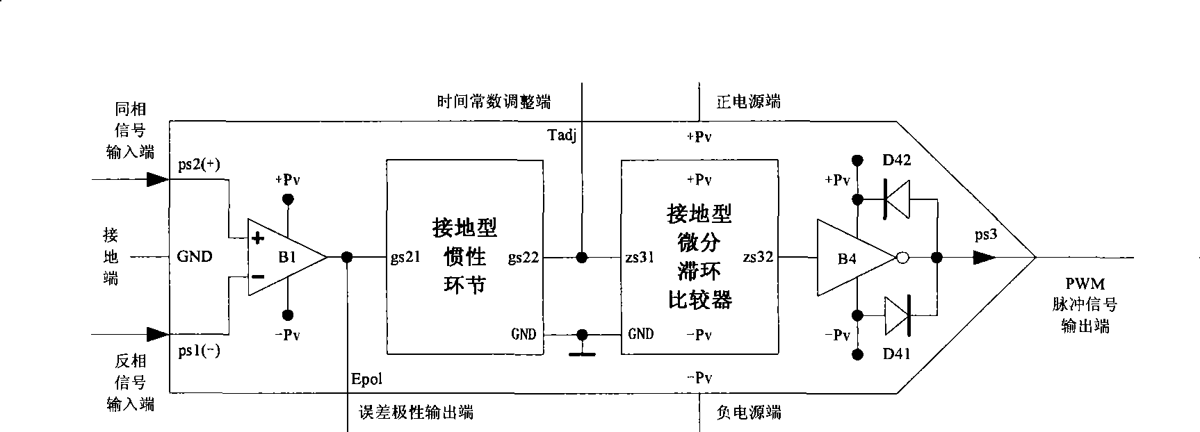
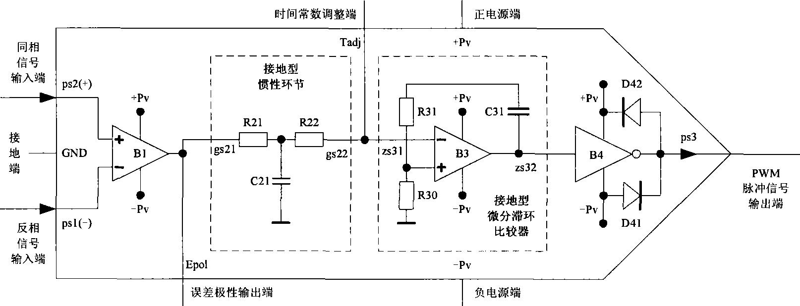
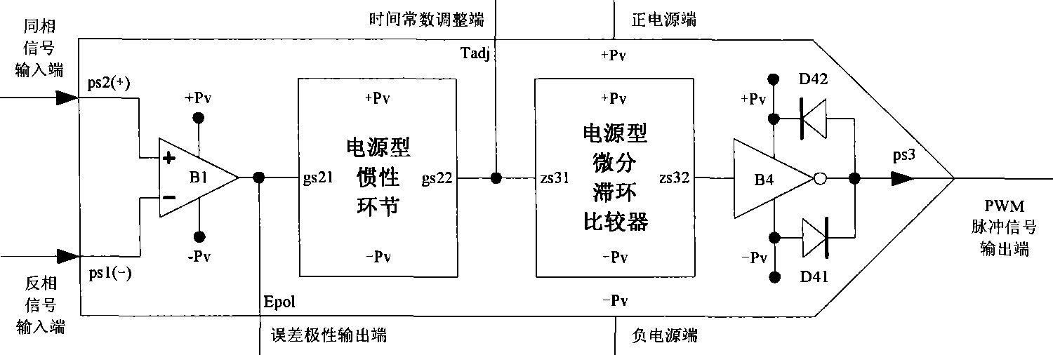
PWM pulse controller
A technology of pulse controller and controller, which is applied in the direction of pulse duration/width modulation, general control system, control/regulation system, etc., and can solve problems such as complex circuits and algorithms, high cost, and poor performance
- Summary
- Abstract
- Description
- Claims
- Application Information
AI Technical Summary
Problems solved by technology
Method used
Image

Examples
Embodiment 1
[0069] PWM waveform generator
[0070] The schematic diagram of the structure of the PWM waveform generator is as follows: Figure 20 shown.
[0071] The PWM waveform generator is composed of a PWM pulse controller, an RC filter, and an output buffer unit. The PWM waveform generator inputs a given signal, and outputs a PWM pulse signal through the PWM controller together with the feedback variable input. The PWM pulse signal passes through the RC The filter output is a pulsating DC voltage feedback variable.
[0072] Suppose: the pulse width difference ratio of the pulse signal waveform (abbreviation: difference ratio) Q is the positive pulse width T 2 with negative pulse width T 1 The difference (T 2 -T 1 ) and the whole period (T 2 +T 1 )Ratio.
[0073] which is:
[0074] Q = T 2 - T 1 T ...
Embodiment 2
[0082] PWM switching power supply
[0083] The schematic diagram of the structure of the PWM switching power supply is as follows: Figure 22 shown.
[0084]The PWM switching power supply is composed of a variable resistor R0, a PWM pulse controller P1, an inverting high-power driver P2, and an LC filter. The PWM switching power supply inputs a given voltage signal from the variable resistor R0, and outputs a PWM pulse signal through the PWM controller P1 together with the feedback variable input. The PWM pulse signal is amplified by the power of the high-power driver P2 and output smoothly by the waveform of the LC filter. A pulsating DC voltage waveform, and the output divided by the resistors R1 and R2 is connected to the input terminal of the PWM controller P1 as a feedback variable.
[0085] The working waveform of PWM switching power supply is as follows: Figure 23 shown.
[0086] Selecting the proper oscillation frequency of the PWM output pulse signal and the para...
Embodiment 3
[0090] Class D Audio Power Amplifier
[0091] The schematic diagram of the class D audio power amplifier structure is as follows: Figure 24 shown.
[0092] Class D audio power amplifier is composed of PWM pulse controller, LC filter and so on. The class D audio power amplifier inputs an audio voltage signal, and the feedback variable is input to the PWM controller through the resistors R1 and R2 respectively, and the PWM controller outputs a PWM pulse signal, and the PWM pulse signal is smoothed by the waveform of the LC filter to output a power audio voltage. Push the speaker to produce sound. PWM pulse signal waveform such as Figure 25 shown.
[0093] Due to the effect of resistors R1 and R2, the output voltage of this class D audio power amplifier is proportional to the input audio signal, and its output voltage U o with input voltage U i The relationship between is:
[0094] U o = - R...
PUM
 Abstract
Description
Claims
Application Information