
Method of fast hydrogen passivation to solar cells made of crystalline silicon

A technology of solar cells and crystalline silicon, applied in circuits, photovoltaic power generation, electrical components, etc., can solve the problems of hydrogen passivation effect damage, hydrogen atoms detachment from wafers, etc., to reduce harmful effects and improve performance

Active Publication Date: 2009-04-22
IND TECH RES INST
View PDF4 Cites 10 Cited by
  • Summary
  • Abstract
  • Description
  • Claims
  • Application Information

AI Technical Summary

Problems solved by technology

Because electrode production often requires high-temperature heating and baking steps, and the bond between hydrogen and silicon will decompose above 400°C, causing hydrogen atoms to detach from the wafer, so the hydrogen passivation effect described in the previous paragraph will be destroyed

Method used


Image

  • Method of fast hydrogen passivation to solar cells made of crystalline silicon
  • Method of fast hydrogen passivation to solar cells made of crystalline silicon
  • Method of fast hydrogen passivation to solar cells made of crystalline silicon

Examples


Embodiment 1

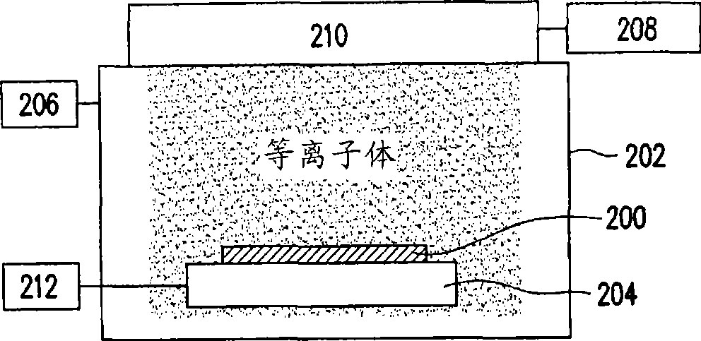
[0052] In this embodiment, the bottom pressure of the vacuum chamber is 10 -6 Torr, then input hydrogen as the working gas and increase the pressure to 2mTorr. The plasma was excited with RF power (13.56 MHz) through an inductively coupled antenna. The power is 200W. The plasma density is about 10 11 cm -3 , and a pulse voltage of -4kV was used to bias the solar cell. The pulse width is 10 μsec and the pulse frequency is 200 Hz. This experiment does not provide power to heat the solar cell, because the temperature of the sample will increase to about 100 °C during plasma ion implantation. The total process time is 10 minutes.

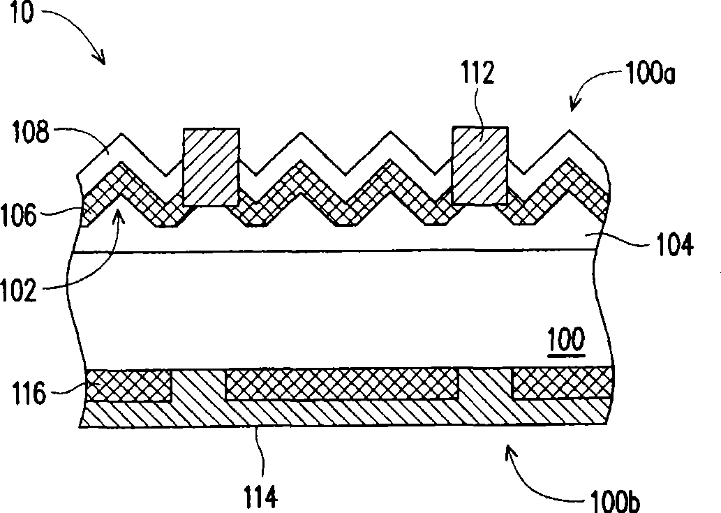
[0053] Solar cells are made of p-type, boron-doped to 1×10 20 cm -3 Made of polysilicon wafer (mc-Si wafer). Their mean grain size is about 5 mm. Corner pyramid structures have been fabricated on the surface of the wafer. N + P bonding uses POCL at 850°C 3 Diffused for 20 minutes to make. Next, a layer of 20nm SiO is formed by a thermal ox...

Embodiment 2

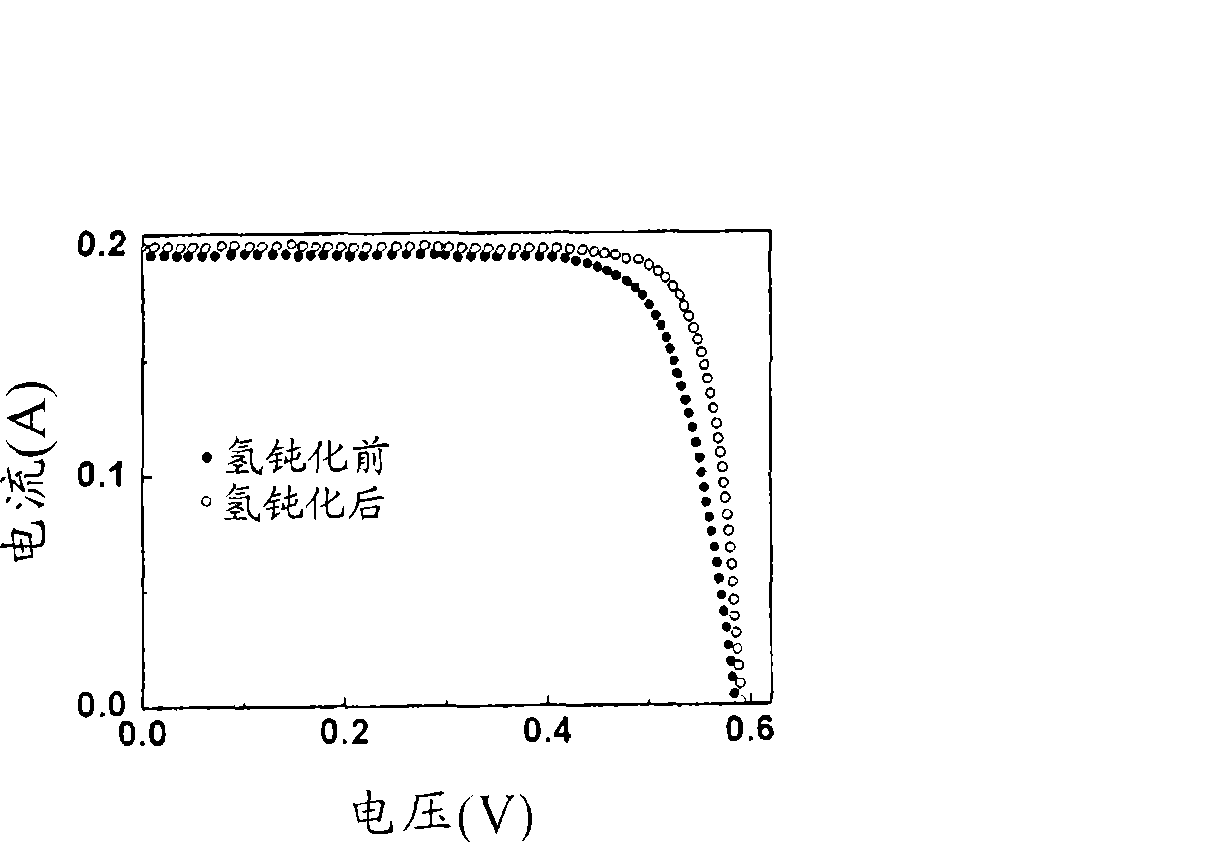
[0056] In this example, a monocrystalline silicon solar cell was fabricated. The structure and process of making are the same as the first embodiment. In addition, the plasma conditions and processing conditions are also the same. Figure 4 For the comparison of the current-voltage characteristics of solar cells before and after the hydrogen passivation process, the results show that the fill factor results increased from 75.00% to 80.77%. At the same time, the short-circuit current increased from 0.23A to 0.25A, and the open-circuit voltage also increased from 0.59V to 0.6V. These improvements increased the conversion efficiency from 14.25% to 17.06%.

[0057] In summary, compared with the prior art, the present invention can greatly reduce the time and cost of the hydrogen passivation process, and effectively improve the efficiency of crystalline silicon solar cells. Moreover, the equipment used is relatively simple and economical, and is suitable for mass production. Th...


PUM


Abstract

A method of improving efficiency of solar cells made of crystalline silicon, including monocrystalline silicon, multicrystalline silicon and polycrystalline silicon is provided. In the method, a negative bias pulse is applied to solar cells at a predetermined voltage, a predetermined frequency, and a predetermined pulse width while immersing the solar cells in a hydrogen plasma. Hydrogen ions are attracted and quickly implanted into the solar cells. Thus, the passivation of crystal defects in the solar cells can be realized in a short period. Meanwhile, the properties of an antireflection layer cannot be damaged as proper operating parameters are used. Consequently, the serious resistance of the solar cells can be significantly reduced and the filling factor increases as a result. Further, the short-circuit current and the open-circuit voltage can be increased. Therefore, the efficiency can be enhanced.

Description

【Technical field】 [0001] The invention relates to a method for hydrogenation of a silicon substrate. In particular, a rapid hydrogenation process is used to passivate silicon crystal defects in crystalline silicon (crystalline silicon, c-Si) solar cells. The aforementioned crystalline silicon includes monocrystalline silicon (monocrystalline, m-Si), polycrystalline silicon (multicrystalline, mc-Si) and polycrystalline thin film (poly-Sithin film). 【Background technique】 [0002] Solar cells are a very promising clean energy source that can generate electricity directly from sunlight. However, at present, the production cost of solar cells must be effectively reduced before solar cells can be widely accepted and become the main source of electricity. Studies indicate that silicon wafers already account for more than one-third of the total cost of crystalline silicon solar cell modules. Therefore, in order to reduce costs, using polycrystalline silicon (mc-Si) or polycrysta...

Claims


Application Information

Patent Timeline
Patent Type & Authority Applications(China)
IPC IPC(8): H01L31/18
CPCH01L31/1804H01L31/1868Y02E10/50Y02E10/547Y02P70/50
Inventor 孙文檠陈建勋甘炯耀黄振昌寇崇善王志伟林建佑
Owner IND TECH RES INST
Learn More