
Hard coat film and optically functional film

A hard coating film and hard coating technology, applied in the direction of optics, optical components, coatings, etc., to achieve the effects of maintaining transparency, improving adhesion, and excellent adhesion

Active Publication Date: 2009-06-17
TOYOBO CO LTD
View PDF7 Cites 6 Cited by
  • Summary
  • Abstract
  • Description
  • Claims
  • Application Information

AI Technical Summary

Problems solved by technology

[0030] That is, a hard coat film that can maintain high hardness and has excellent adhesion to high-speed cutting required in recent years, especially adhesion to a hard coat layer containing inorganic particles, cannot be obtained by the current technology.

Method used


Image

  • Hard coat film and optically functional film
  • Hard coat film and optically functional film
  • Hard coat film and optically functional film

Examples


Embodiment 1

[0466] (1) Preparation of coating liquid

[0467] The coating liquid used in the present invention is prepared as follows.

[0468] Dimethyl terephthalate (95 parts by mass), dimethyl isophthalate (95 parts by mass), ethylene glycol (35 parts by mass), neopentyl glycol (145 parts by mass), zinc acetate (0.1 parts by mass) and antimony trioxide (0.1 parts by mass) were placed in a reaction container, and a transesterification reaction was performed at 180° C. for 3 hours. Then add isophthalic acid-5-sodium sulfonate (6.0 parts by mass), carry out esterification reaction at 240°C for 1 hour, and then carry out polycondensation reaction at 250°C under reduced pressure (10-0.2mmHg). hours, a copolyester with a number average molecular weight of 19500 and a softening temperature of 60°C was obtained.

[0469] 7.5 parts by mass of a 30 mass % aqueous dispersion of the obtained copolyester (A), a 20 mass % aqueous solution ( 11.3 parts by mass of Elastron H-3 manufactured by Daiic...

Embodiment 2

[0486] As the surfactant used for the coating liquid in Example 1, 10% by mass of the fluorine-based cationic surfactant (manufactured by Neoos Co., Ltd., Futa-Jient 310) pretreated in the same manner as in Example 1 Except that the aqueous solution was used as the coating liquid B, it carried out similarly to Example 1, and obtained the adhesive modified polyester film.

[0487] Then, the hard coat layer C containing inorganic particles was laminated on one side in the same manner as in Example 1 on the surface of the adhesive modified layer B of the adhesive modified base film to obtain a hard coat film.

Embodiment 3

[0489] The temperature of each heat-fixing zone in the heat-fixing process of Example 1 is set as follows: the temperature of the first heat-fixing zone is 190°C, the temperature of the second heat-fixing zone is 205°C, and the temperature of the third heat-fixing zone is 220°C , the temperature in the fourth heat-fixing zone was 220° C., and the same method as in Example 1 was used to obtain an adhesively modified polyester film.

[0490] Then, the hard coat layer C containing inorganic particles was laminated on one side in the same manner as in Example 1 on the surface of the adhesive modified layer B of the adhesive modified base film to obtain a hard coat film.


PUM

PropertyMeasurementUnit
particle diameteraaaaaaaaaa
thicknessaaaaaaaaaa
thicknessaaaaaaaaaa

Abstract

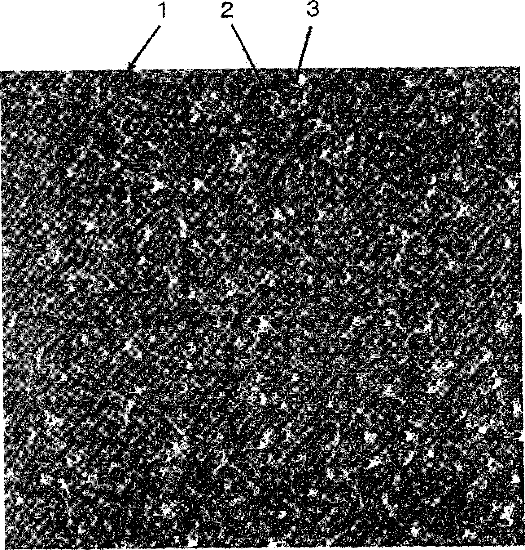
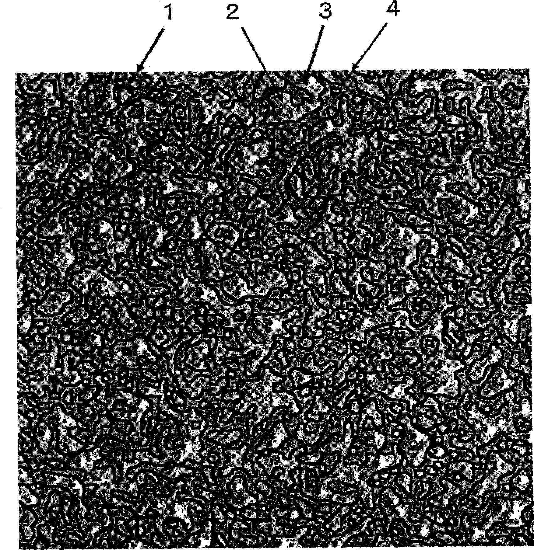
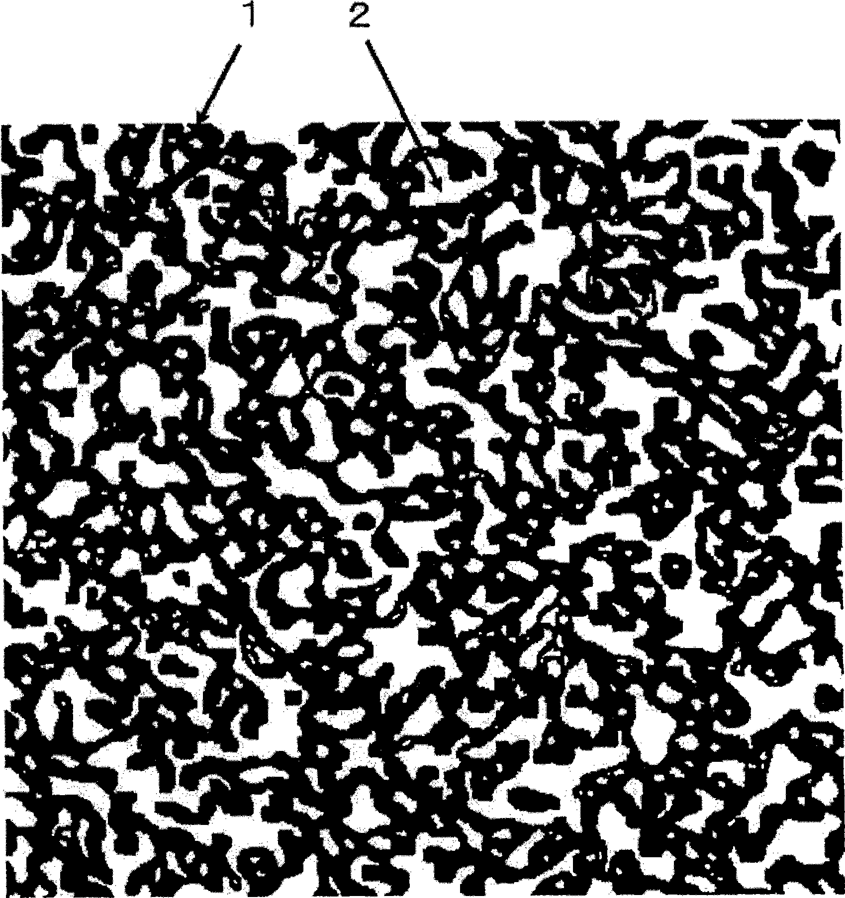
A hard coat film having an adherence modifying substratum film consisting of adherence modifying layer (B) containing copolymerized PEs and PU superimposed on one major surface or both major surfaces of thermoplastic resin film (A) and having, superimposed on the surface of the adherence modifying layer (B) on either one major surface of the substratum film, hard coat layer (C) containing inorganic microparticles, characterized in that the adherence modifying layer (B) has a micro phase separation structure or nano phase separation structure of PEs phase and PU phase, and that when a cut plane of the hard coat film is observed in a phase measurement mode by the use of a scanning probe microscope, the ratio of area of PU phase of adherence modifying layer (B) in the zone from interface of the adherence modifying layer (B) with the hard coat layer (C) to a depth of 20 nm is in the range of 30 to 60%.

Description

technical field [0001] The present invention relates to a hard coat film mainly used for display parts, and an antireflection film using the film, a light diffusion sheet, a prismatic lens sheet, a near-infrared ray blocking film, a transparent conductive film, an antiglare film, etc. membrane. Specifically, it relates to adhesion between a substrate film, a hard coat layer containing inorganic particles, and other optically functional layers (hard coat layer, light diffusion layer, prism layer, infrared absorption layer, transparent conductive layer, antiglare layer, etc.) A hard coat film with excellent scratch resistance and excellent scratch resistance and an optical functional film using the hard coat film. Background technique [0002] In general, hard coat films used in display components such as liquid crystal displays (LCD) and plasma display panels (PDP) are laminated with thermoplastic resin films and hard coat (HC) layers with adhesive modified resin layers inte...

Claims


Application Information

Patent Timeline
Patent Type & Authority Applications(China)
IPC IPC(8): B32B27/36B32B27/40G02B1/10G02B1/11C08J7/043C08J7/044C08J7/046C08J7/056G02B1/14G02B1/18
CPCC08G18/0833C08G18/7642C08G18/4238C08J7/04C08J2475/04C08J2467/02C08G18/10G02B1/10C08J7/043C08J7/046C08J7/044C08J7/056C08G18/3872C08G18/286B32B27/36B32B27/40B82Y40/00G02B1/11G02B1/14
Inventor 水野直树杉原秀纪岩出茂则西野泰弘野濑克彦铃木利武森重地加男
Owner TOYOBO CO LTD
Learn More