
Technological process for flue gas purification

A technology for process flow and flue gas purification, applied in chemical instruments and methods, separation of dispersed particles, separation methods, etc., can solve problems such as catalyst pollution, poisoning, catalyst sintering, etc., to reduce adverse effects, shorten the process flow, and simplify the process The effect of the process

Active Publication Date: 2011-10-12
LONGYAN QIANGLONG METAL FIBER
View PDF3 Cites 0 Cited by
  • Summary
  • Abstract
  • Description
  • Claims
  • Application Information

AI Technical Summary

Problems solved by technology

The disadvantage is that the catalyst is in the high dust flue gas, and its service life will be affected by the following factors
[0008] ① K, C in fly ash a , S I 、A s Contaminate or poison the catalyst;
[0010] ③ If the flue gas temperature is too high, the catalyst will sinter or fail;
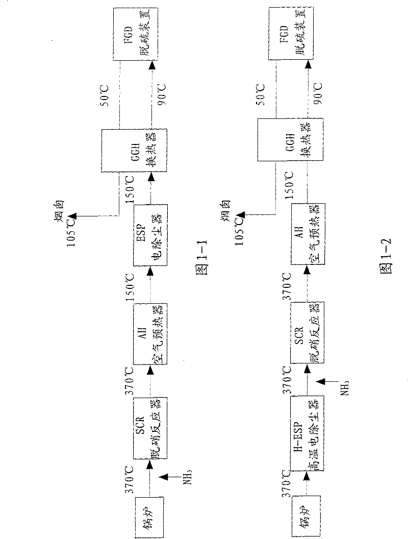
[0014] The second arrangement is Figure 1-2 In the high-temperature and low-dust arrangement shown, the denitrification reactor is placed between the high-temperature electrostatic precipitator (H-ESP) and the air preheater behind the economizer (300-400°C). Ash pollutes the catalyst, wears and clogs the denitrification reactor, but it is difficult for the general electrostatic precipitator to operate normally at a high temperature of 300-400 ° C, and the reliability is not high, so it is generally not used
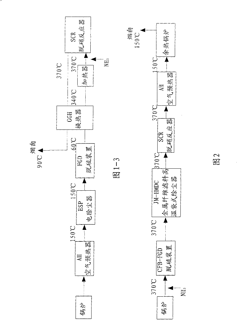
[0015] The third arrangement is Figure 1-3 In the low-temperature and low-dust arrangement shown, the denitrification reactor is placed after the wet FGD system, and the catalyst will not be affected by fly ash and SO 3 However, due to the low smoke temperature, it is generally necessary to use a gas-gas heat exchanger or add a fuel or natural gas burner to increase the smoke temperature to the activation level of the catalyst, increasing energy consumption and operating costs

Method used


Image

  • Technological process for flue gas purification
  • Technological process for flue gas purification
  • Technological process for flue gas purification

Examples


example 1

[0064] Example 1: The porous support tube is made of a perforated steel plate with an outer diameter of 60 mm and a tube wall of 2 mm, and is wrapped with a layer of ceramic fiber (fiber cotton) on the outside, with a thickness of 6 mm, an average fiber diameter of 5 um, and a fiber cotton porosity of 85%; The outside of the fiber cotton is tightly wrapped with one deck of stainless steel wire mesh (outer protection mesh), the wire mesh is 40 mesh, and the silk warp is 0.25mm.

example 2

[0065] Example 2: The porous support tube is made of a perforated plate with an outer diameter of 150 mm and a tube wall of 3 mm, wrapped with two layers of wire mesh (inner support net), and then wrapped with a layer of 3 mm thick stainless steel coarse fiber cotton (fiber Cotton) with a fiber diameter of 20um, and then wrap a layer of 1mm thick stainless steel fine fiber cotton (fiber cotton), with a fiber diameter of 6um, and finally wrap two layers of 50-mesh 0.125mm silk warp square mesh outside (outer protection net) .

example 3

[0066] Example 3: The outer diameter of the porous support tube is only 20mm, the length is 1m, the thickness of the fiber cotton is only 1mm, the width is 8cm, and the length is 2m. The net and the fiber cotton are wound helically on the porous support tube with a distance of 4 cm and 25 turns. The tight winding makes the fiber cotton void ratio 70%. Both ends are cut evenly and tightened with an outer hoop to add 30 mesh.


PUM


Abstract

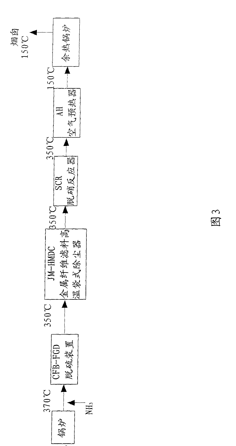
The invention discloses a technological process for flue gas purification, including the steps of flue gas desulphurization, dust collection and denitration, wherein above 300 DEG C, the flue gas is pThe invention discloses a technological process for flue gas purification, including the steps of flue gas desulphurization, dust collection and denitration, wherein above 300 DEG C, the flue gas is processed by the operation of dust collection by a high temperature bag type dust collector made of metal fibre filter materials, and then is processed by the operation of denitration by a selective carocessed by the operation of dust collection by a high temperature bag type dust collector made of metal fibre filter materials, and then is processed by the operation of denitration by a selective catalytic reduction denitration reactor. The invention can effectively give full play to the advantages of the single technology of dust collection, desulphurization and denitration, avoids the disadvantalytic reduction denitration reactor. The invention can effectively give full play to the advantages of the single technology of dust collection, desulphurization and denitration, avoids the disadvantages of the single technology, and especially enables the SCR denitration to have higher activity under the high temperature of the flue gas, thereby greatly reducing the adverse effect on the SCR detages of the single technology, and especially enables the SCR denitration to have higher activity under the high temperature of the flue gas, thereby greatly reducing the adverse effect on the SCR denitration; further more, SCR catalyst which has a smaller passage and a larger surface area can be used, and the heat energy of the high temperature flue gas not only can be utilized by an air preheatnitration; further more, SCR catalyst which has a smaller passage and a larger surface area can be used, and the heat energy of the high temperature flue gas not only can be utilized by an air preheater AH, but also can be further utilized by installing a waste heat boiler, thereby simplifying and shortening the entire technological process.er AH, but also can be further utilized by installing a waste heat boiler, thereby simplifying and shortening the entire technological process.

Description

technical field [0001] The invention relates to a flue gas purification (desulfurization, dust removal, denitrification) process flow. Background technique [0002] The existing filter materials mainly include various chemical fiber woven fabrics or needle-punched felts, whose working temperature is below 260°C, and are widely used in bag-type dust collectors in coal-fired power plants, metallurgy, cement and other industries. There are only high-temperature electrostatic precipitators and ceramic fiber and porous ceramic precipitators, but the reliability of the former is poor, and the resistance of the latter is very large, so it has not been widely used. [0003] The metal fiber filter material mainly made of stainless steel fiber and iron-chromium-aluminum fiber is a new type of filter material, which has a higher service temperature and higher strength than glass fiber and chemical fiber. The stainless steel fiber filter material can be used for a long time below 450 °...

Claims


Application Information

Patent Timeline
Patent Type & Authority Patents(China)
IPC IPC(8): B01D53/75
Inventor 黄朝强方惠会
Owner LONGYAN QIANGLONG METAL FIBER
Learn More