
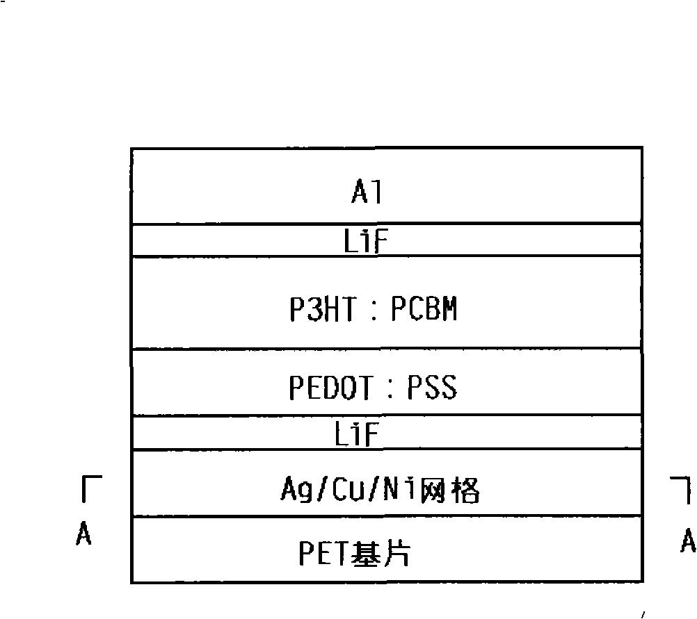
Flexible polymer solar battery of anode layer of metal grid and preparation method

A flexible polymer and solar cell technology, which is applied in the coating process of metal materials, coatings, circuits, etc., can solve the problems of low adhesion, limited space for device improvement efficiency, high anode square resistance, etc., and achieve energy conversion efficiency And performance improvement, improvement of film formation, enhanced balance effect

Inactive Publication Date: 2009-09-23
HEBEI UNIVERSITY
View PDF0 Cites 36 Cited by
  • Summary
  • Abstract
  • Description
  • Claims
  • Application Information

AI Technical Summary

Problems solved by technology

[0003] At present, the indium tin oxide thin film (ITO) anode based on flexible substrate has high square resistance (generally 50-100Ω / □) and low adhesion ability, so it is not suitable as an anode material
Y.Zhou et al. reported that a flexible device was prepared by spin-coating a polythiophene PH500 instead of ITO on polyethylene terephthalate (PET), and its photoelectric conversion efficiency was about 2%, because of its high square resistance (230Ω / □ ), which limits the space for device efficiency improvement, so it is necessary to develop new anode materials to meet the requirements of flexible substrate polymer solar cells

Method used


Image

  • Flexible polymer solar battery of anode layer of metal grid and preparation method
  • Flexible polymer solar battery of anode layer of metal grid and preparation method
  • Flexible polymer solar battery of anode layer of metal grid and preparation method

Examples


Embodiment 1

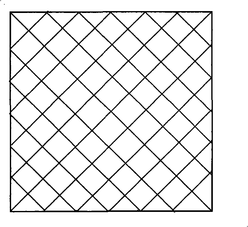
[0030] A. Prepare the grid template: firstly, the ultrafine particle dry board or PCB film is processed by laser exposure and development to make a grid template with a grid pattern, and the line width, line spacing, and density of the grid are adjusted to obtain different grid patterns;

[0031] B. Preparation of metal grids on flexible PET substrates: Print a template with a grid pattern on a silver halide photosensitive film, or scan the grid pattern on a silver halide photosensitive film with a laser; after developing, fixing, and curing , to obtain metal silver grid pattern on the flexible substrate; and then electroless copper plating and electroless nickel plating to obtain silver, copper and nickel grid conductive film anode layer;

[0032] The electroless copper plating on the metal silver grid pattern is to use the electroless plating solution with a pH value of 12.5 at 25°C: copper sulfate 60mM / L, triethanolamine 180mM / L, potassium ferrocyanide 0.002mM / L, copper pla...

Embodiment 2

[0039] Embodiment 2: The preparation method is the same as that of Embodiment 1, except that the film thickness of the active layer is controlled at 120nm.

Embodiment 3

[0040] Embodiment 3: The preparation method is the same as that of Embodiment 1, except that the film thickness of the active layer is controlled at 90 nm.


PUM

PropertyMeasurementUnit
Thicknessaaaaaaaaaa

Abstract

The invention relates to a flexible polymer solar battery of an anode layer of a metal grid, which comprises a flexible substrate, an anode layer, a hole transport layer, an active layer, an electron transfer layer and an Al electrode cathode and is characterized in that the anode layer is made from one or more of composition metal wire grid materials of Ag, Cu, and Ni. In the solar battery, a silver, copper and nickel (Ag: Cu: Ni) metal grid / LiF combined electrode is used as the anode; compared with the battery prepared by a common flexible substrate ITO electrode, the flexible solar battery prepared by taking P3HT / PCB as the active layer can show up better performance; after a layer of lithium fluoride (LiF) layer with the thickness of 2nm is added between the Ag: Cu: Ni metal grid and the polythiophene derivative doped polystyrolsulfon acid (PEDOT: PSS) layer, the film formation of PEDOT: PSS on the surface of the anode is improved, the balance between the hole and the electron transport is enhanced, and compared with the battery with the common flexible substrate ITO electrodes, the energy conversion efficiency is obviously improved.

Description

technical field [0001] The invention relates to a flexible polymer solar cell with a metal grid anode layer and a preparation method thereof, and belongs to the technical field of organic polymer heterojunction solar cells. Background technique [0002] Organic polymer heterojunction solar cells have received extensive attention in recent years because of their outstanding advantages such as simple preparation, low cost, light weight, and flexible devices, and flexible substrate polymer solar cells have their unique and extensive application prospects. , How to improve the photoelectric conversion efficiency of polymer solar cells to meet the requirements of flexibility and practicality is a key problem to be solved in the field of polymer solar cells with flexible substrates. [0003] Currently, indium tin oxide thin film (ITO) anodes based on flexible substrates have high square resistance (generally 50-100Ω / □) and low adhesion, so they are not suitable as anode materials....

Claims


Application Information

Patent Timeline
IPC IPC(8): H01L51/42H01L51/44H01L51/46H01L51/48C23C14/24C23C14/06C23C18/40C23C18/34
CPCY02E10/50Y02E10/549
Inventor 杨少鹏傅广生柴老大邹竞陈金忠
Owner HEBEI UNIVERSITY
Learn More