A thermal plasma and coal dust mixing structure applied to acetylene preparation process through catalytic cracking

A technology of thermal plasma and mixed structure, applied in the direction of organic chemistry, can solve problems such as low coal powder conversion rate, economical impact, blockage, etc., and achieve the goal of improving coal powder conversion rate, improving mixing efficiency, and increasing acetylene yield Effect

Active Publication Date: 2009-10-07
TSINGHUA UNIV
View PDF0 Cites 12 Cited by
  • Summary
  • Abstract
  • Description
  • Claims
  • Application Information

AI Technical Summary

Problems solved by technology

[0005] The plasma jet in the mixer channel in the process of plasma coal cracking to acetylene has the characteristics of high temperature, high enthalpy, and high speed, and has a certain temperature and velocity distribution on the cross-section of the mixer channel, and the accelerated pulverized coal is difficult to Injected into the high-temperature zone in the middle of the plasma jet, a large amount of coal powder is heated and reacted in the area close to the wall surface, and because the wall surface temperature is relatively low, the incompletely heated coal powder will stick to the wall surface, causing coking and blockage of the reactor wall. resulting in interruption of operations
In addition, pulverized coal cannot be fully mixed with the high-temperature plasma jet, which will also lead to low conversion rate of pulverized coal and low gas phase volume content of acetylene in the product gas, which will affect the economics of the process.
In addition, different from the laboratory test research, the coal processing capacity per unit effective power of the industrial device is about 10 times that of the laboratory test device, and due to the characteristics of the concentration of plasma jet energy, the geometric size of the reactor does not change. so remarkable
In addition, there are still problems such as the dispersion of high-concentration coal powder in the design of the mixed structure of thermal plasma and coal powder.

Method used


Image

  • A thermal plasma and coal dust mixing structure applied to acetylene preparation process through catalytic cracking
  • A thermal plasma and coal dust mixing structure applied to acetylene preparation process through catalytic cracking
  • A thermal plasma and coal dust mixing structure applied to acetylene preparation process through catalytic cracking

Examples


Embodiment 1

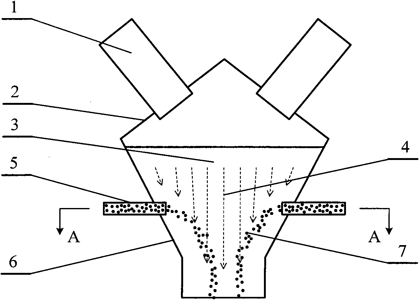
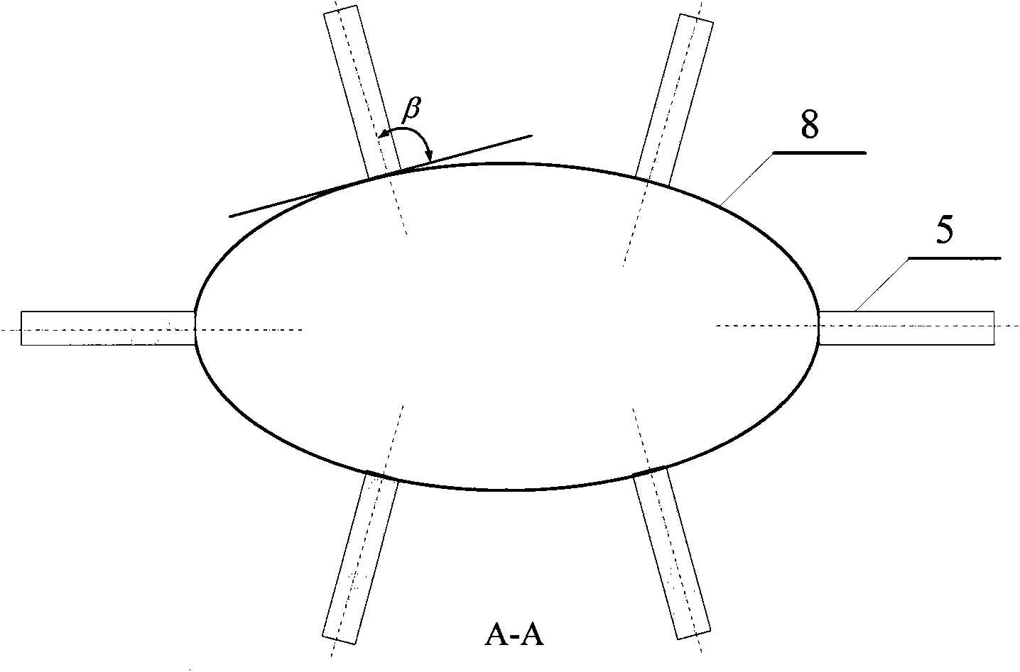
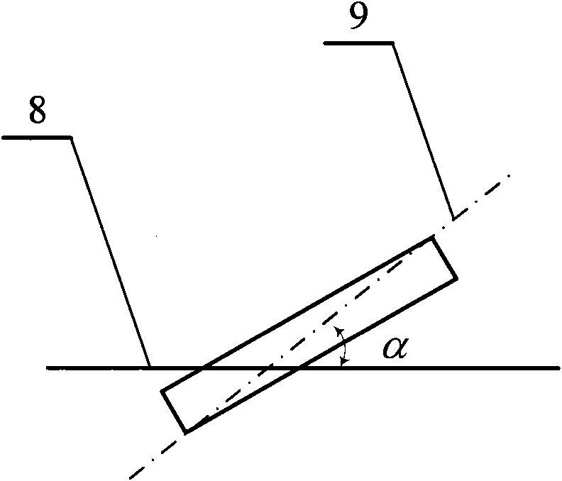
[0029] A thermal plasma and coal powder mixing structure applied to the process of coal cracking to produce acetylene, including a plasma torch 1, a thermal plasma jet mixing zone 2, a gas-solid down-bed mixer channel 3, and a The pulverized coal nozzle 5 ( figure 1 ). Such as figure 2 As shown, the cross-section 8 of the channel of the gas-solid down-bed mixer is elliptical, and the ellipse changes uniformly with the flow direction of the thermal plasma. The largest ellipse has a major axis of 120 mm, a minor axis of 80 mm, and the smallest elliptical major axis of 60 mm. , the minor axis length is 30mm; the number of pulverized coal nozzles 5 is 6, and they are installed at 8 cross-sections of the gas-solid down-bed mixer channel at the same height, where the cross-sectional ellipse has a major axis length of 80 mm, a minor axis length of 40 mm, and a length of 40 mm. The ratio of the axis to the minor axis is 2, and the ratio of the cross-sectional perimeter P of the cro...

Embodiment 2

[0032]A thermal plasma and coal powder mixing structure applied to the process of coal cracking to produce acetylene, including a plasma torch 1, a thermal plasma jet mixing zone 2, a gas-solid down-bed mixer channel 3, and a The pulverized coal nozzle 5 surrounding the thermal plasma jet in the channel 3 of the gas-solid down-bed mixer (Fig. 4(a)). The distribution of pulverized coal nozzles is shown in Figure 4(b) and Figure 4(c). The cross-section 8 of the gas-solid down-bed mixer channel is elliptical, and the ellipse changes uniformly with the flow direction of the hot plasma. The maximum elliptical length The axis length is 120mm, the minor axis length is 80mm, the smallest ellipse has a major axis length of 60mm, and a minor axis length of 30mm; the number of pulverized coal nozzles 3 is 6, and they are installed on the cross-section 8 of the two gas-solid down-bed mixer channels 20mm apart. Above (Fig. 4(a)), four pulverized coal nozzles 3 are arranged on the higher cr...

Embodiment 3

[0035] A thermal plasma and coal powder mixing structure applied to the process of coal cracking to acetylene, including a plasma torch 1, a thermal plasma jet mixing zone 2, and a gas-solid down-bed mixer channel 3, located below the plasma torch 1 and surrounded by The pulverized coal nozzle 5 around the thermal plasma jet in the gas-solid down-bed mixer channel 3, and the flow blocking member 10 ( Figure 5 ). The distribution of pulverized coal nozzles is as follows: figure 2 As shown, there is a blocking member 10 at 15 mm above each pulverized coal nozzle 5, and the cross-section 8 of the gas-solid down-bed mixer channel is elliptical, and the ellipse changes uniformly with the flow direction of the thermal plasma, and the maximum elliptical length The axis length is 120mm, the minor axis length is 80mm, the smallest ellipse has a major axis length of 60mm, and a minor axis length of 30mm; the number of pulverized coal nozzles 5 is 6, and they are installed at 8 cross-...


PUM


Abstract

The present invention discloses a thermal plasma and coal dust mixing structure applied to acetylene preparation process through catalytic cracking in the technical field of chemical equipment and consists of plasma torch, plasma jet mixing zone, gas-solid downer mixer channel, and the coal powder nozzles under the plasma torch and around the plasma jet inside the gas-solid downer mixer channel. The cross section of the mixer channel is a two-dimensional closed pattern and is changed along the axial direction of the plasma jet; the coal powder nozzles are distributed on the cross section of the mixer channel at a same or different height; the cross section of the outlet of coal powder ash nozzle is in a wide and flat shape and its installation angle may be adjusted in the whole spatial range. The present invention may realize good mixing between the coal powder sprayed out of coal powder nozzles and thermal plasma jets and can effectively raise coal ash conversion rate and acetylene yield and alleviate reactor coking.

Description

technical field [0001] The invention relates to a thermal plasma and coal powder mixing structure used in the process of coal cracking to produce acetylene, and belongs to the technical field of chemical equipment. Background technique [0002] Acetylene is an important basic organic chemical raw material. The industrial methods for producing acetylene mainly include calcium carbide method, methane partial oxidation method and methane arc cracking method. Among them, the calcium carbide method acetylene process is mature and accounts for an absolute proportion in industrial production, but the pollution and energy consumption are relatively high. Plasma pyrolysis of coal to acetylene is a new and promising route for direct chemical conversion of coal. Since the 1990s, Chinese scholars and engineering technicians have carried out a lot of basic research and engineering research in this field. Because my country's oil and gas resources are relatively scarce, but coal resourc...

Claims


Application Information

Patent Timeline
Patent Type & Authority Applications(China)
IPC IPC(8): C07C11/24
Inventor 程易颜彬航吴昌宁双玥章莉
Owner TSINGHUA UNIV
Why Eureka
Try Eureka