Engraved plate and base material having conductor layer pattern using the engraved plate
一种导体层、凹版的技术,应用在透光性电磁波屏蔽部件,图形化金属箔领域,能够解决折断、生产率下降、工序数增加等问题
- Summary
- Abstract
- Description
- Claims
- Application Information
AI Technical Summary
Problems solved by technology
Method used
Image
Examples
Embodiment 1A
[0840] (formation of convex figure)
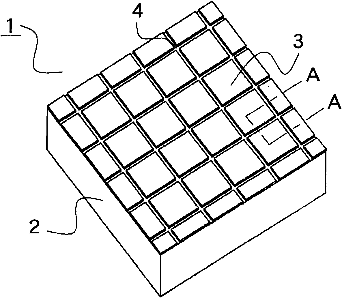
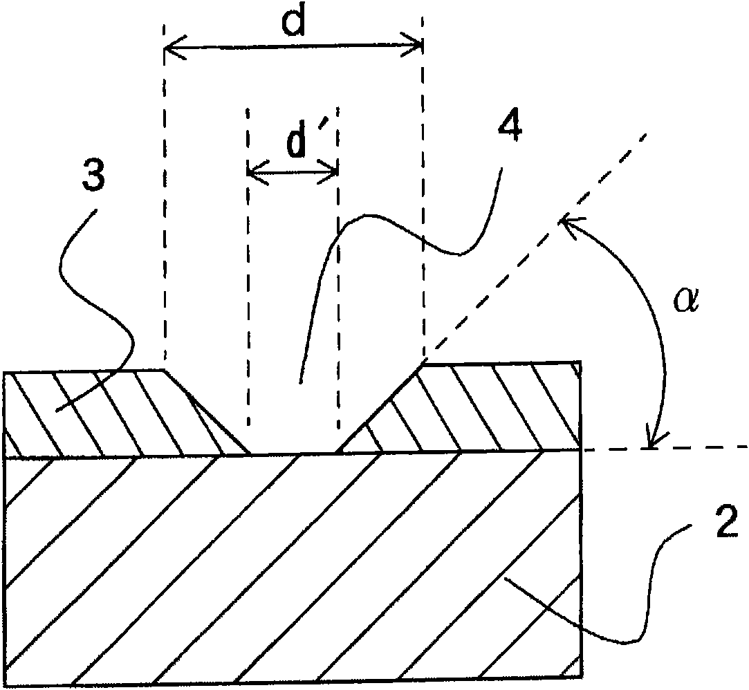
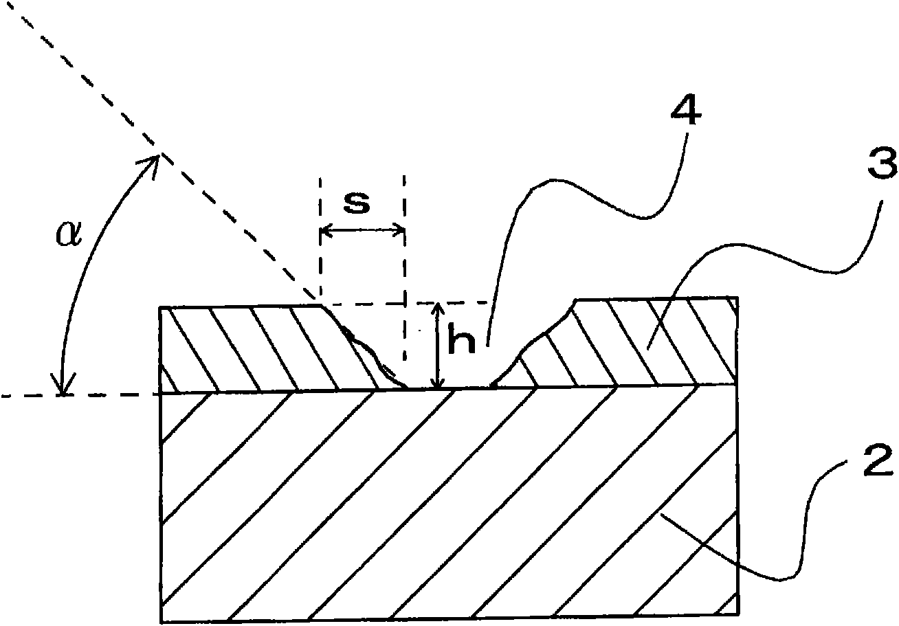
[0841] A resist film (PhoTec RY3315, 10 μm thick, manufactured by Hitachi Chemical Industries, Ltd.) was attached to both sides of a 150 mm square stainless steel plate (SUS316L, mirror polished, 300 μm thick, manufactured by Nisshin Steel Co., Ltd.) (corresponding to Figure 3A ). The bonding conditions were carried out at a roll temperature of 105° C., a pressure of 0.5 MPa, and a line speed of 1 m / min. Then, the line width of the light-transmitting part is 15 μm, the line spacing is 300 μm, and the off-angle is 45° (in a regular quadrilateral, the lines are arranged at an angle of 45 degrees relative to the side of the regular quadrilateral) and the grid-like figure is set in a 120m square Dimensional negative-type films were placed on one side of a stainless steel plate. Using an ultraviolet irradiation device, in a vacuum below 600mmHg, from the top and bottom of the stainless steel plate with the negative film placed, 120mJ / cm 2 U...
Embodiment 2A
[0859] (formation of convex figure)
[0860] A liquid resist (ZPN-2000, manufactured by Nippon Zeon Co., Ltd.) was coated on both sides of a 150 mm square titanium plate (pure titanium, mirror-polished, 400 μm thick, manufactured by Nippon Metal Corporation). Coating was performed three times to obtain a resist film with a thickness of 6 μm. After prebaking at 110°C for one minute, the line width of the light-transmitting part is 5 μm, the line spacing is 300 μm, and the off-angle is 45° (in a regular quadrilateral, the lines are arranged at an angle of 45 degrees relative to the sides of the regular quadrilateral) and A negative-type chromium mask formed with a grid-like pattern in a size of 110mm square was placed on one side of the titanium plate. Use an ultraviolet irradiation device to suck the substrate in a vacuum below 600mmHg, and use 200mJ / cm from the top of the titanium plate with a chrome mask 2 UV rays are irradiated. In addition, at 200mJ / cm 2 Illuminate the ...
Embodiment 3A
[0875] A liquid resist (KMPR-1050, manufactured by Nippon Kayaku Co., Ltd.) was applied to both surfaces of a stainless steel plate (SUS304, 314×150 mm, manufactured by Nisshin Steel Co., Ltd.) in a thickness of 15 μm. After prebaking at 90°C for 10 minutes, the line width of the light-transmitting part is 5 μm, the line spacing is 300 μm, and the off-angle is 45° (in a regular quadrilateral, the lines are arranged at an angle of 45 degrees relative to the sides of the regular quadrilateral) and Two negative-type chrome masks formed with a grid-like pattern in a size of 110 mm square were placed side by side on one side of the stainless steel plate. Use an ultraviolet irradiation device to suck the substrate in a vacuum below 600mmHg, and use 200mJ / cm from the top of the stainless steel plate with a chrome mask 2 UV rays are irradiated. In addition, at 200mJ / cm 2 Illuminate the backside where no mask is placed. After heating at 95°C for 7 minutes, by developing with 2.38% t...
PUM
| Property | Measurement | Unit |
|---|---|---|
| Rockwell hardness | aaaaa | aaaaa |
| width | aaaaa | aaaaa |
| area | aaaaa | aaaaa |
Abstract
Description
Claims
Application Information
 - R&D
- Intellectual Property
- Life Sciences
- Materials
- Tech Scout
- Unparalleled Data Quality
- Higher Quality Content
- 60% Fewer Hallucinations
Browse by: Latest US Patents, China's latest patents, Technical Efficacy Thesaurus, Application Domain, Technology Topic, Popular Technical Reports.
© 2025 PatSnap. All rights reserved.Legal|Privacy policy|Modern Slavery Act Transparency Statement|Sitemap|About US| Contact US: help@patsnap.com


