System and method for quantitative detection of test strips on basis of continuous fluorescent-substance markers

A technology for quantitative detection and fluorescence, which is used in biological testing, fluorescence/phosphorescence, chemical instruments and methods, etc.

Active Publication Date: 2012-08-08
马义才
View PDF3 Cites 5 Cited by
  • Summary
  • Abstract
  • Description
  • Claims
  • Application Information

AI Technical Summary

Problems solved by technology

The disadvantages are: (1) The patent application number only describes the production of quantum dot marking test strips, but does not disclose the corresponding supporting instrument detection system. The detection needs to be carried out with the help of other ultraviolet detectors, and it is only a qualitative detection , cannot achieve quantitative detection
(2) The use of ultraviolet detection is harmful to the human body and unsafe to operate
(3) The objectivity of the measurement results is poor
Since the tester judges the test result by observing the fluorescence intensity of the test strip and the quality control zone under ultraviolet light with the naked eye, the test result is easily affected by the tester's experience and is highly subjective. The same test strip is in different states. It is possible to make different or even wrong judgment results, especially for those samples with extremely low target content, the fluorescence emitted by ultraviolet light is very weak, it is more difficult to judge the results with the naked eye, and the sensitivity is low
(4) Cannot monitor the dynamic process of biological reactions
Immunochromatography is a dynamic reaction process. The fluorescence produced by the quantum dot label particles in the siphon migration state on the test strip belongs to the dynamic category. Obviously, the ultraviolet visual method cannot observe and analyze this dynamic reaction process, so it is impossible to go deeper. To study the immunochromatographic reaction process
Even if the biological reaction fails, the detector cannot analyze the reason for the failure of the reaction well
Chinese patent application No. 200610024566.3 discloses a method of combining quantum dot fluorescent probes to detect biochips to find Chinese medicine targets. This patent also has shortcomings: the detection of the "quantum dot-Chinese medicine ingredients" fluorescent probes involved not only requires other technologies to provide Corresponding protein chips, and its detection also requires additional special equipment
Chinese patent application number 200510059892.3 discloses an optoelectronic rapid diagnostic test system including quantum dot test strip detection, but this patent has not yet developed a ready-made product, and the content is completely different from the present invention
It should also be pointed out that there have been many literature reports on solid-phase detection methods using rare earth nanoparticles as continuous fluorescent markers to label microwell plates, and a corresponding matching detector—time-resolved fluorescence detector (or system) has been developed. ), although its detection can achieve high sensitivity and can achieve quantitative or semi-quantitative detection, but the disadvantage is that the operation is complicated, involving multiple steps such as adding samples, warming bath, washing, color development, termination, detection, etc., and the operation takes 2-4 hours In order to complete the process, there are certain requirements for the operator and the environment. Moreover, in addition to the need for an expensive supporting instrument——time-resolved detector——it also needs other auxiliary equipment such as a plate washer. Therefore, its general application is still limited.

Method used


Image

  • System and method for quantitative detection of test strips on basis of continuous fluorescent-substance markers
  • System and method for quantitative detection of test strips on basis of continuous fluorescent-substance markers
  • System and method for quantitative detection of test strips on basis of continuous fluorescent-substance markers

Examples


Embodiment 1

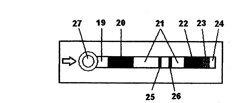
[0067] The test strip rack 28 of the system has test strip slots. The test strip groove is used for placing the test strip 18 marked with persistent fluorescent substance to be tested. The test strip 18 is sequentially provided with a sample pad 19 that overlaps and sticks to each other, a glass fiber membrane bonding pad 20 coated with a persistent fluorescent substance marker, an analysis membrane 21 with a detection belt 25 and a quality control belt 26, a strong water absorption Pad 22 , test strip reaction end point indicator label 23 and test strip identification label 24 .

[0068] The illumination system includes an excitation light source 1 , on the output optical path of the excitation light source 1 there are fiber bundle 2 , collimating illumination lens 3 , dichroic mirror 4 , front mirror group 5 , until the test strip 18 is marked with fluorescent substance. The excitation light source 1 includes a light emitting diode LED or a laser diode. The optical fiber b...

Embodiment 2

[0093] 1. Preparation of each component of the test strip

[0094] (1) Sample pad: choose cellulose membrane, cut into 297x15mm membrane block, put it in a long groove, add blocking solution (pH=7.20.03mol / L phosphate buffer + 5% BSA, +0.1% Tween 20) at room temperature Soak for 30min. Take out the membrane block, dry it at 37°C, and fully dry it for later use.

[0095] (2) Glass fiber membrane binding pad: choose glass fiber membrane, cut into 297x10mm membrane block, put it in a long groove, add the quantum dot-HBsAg monoclonal antibody conjugate solution prepared in advance on it, take out the membrane block, 37 ℃ drying, fully dry for later use.

[0096] (3) Analysis membrane: choose nitrocellulose membrane, cut into 297x25mm membrane block, put it in a long groove, and spray 0.5-5mg / ml HBsAg single point with a film meter at a certain distance from the bottom of the membrane block. Cloning antibody as detection zone and spraying 0.5-5mg / ml goat anti-mouse IgM antibody,...

Embodiment 3

[0128] 1. Preparation of each component of the test strip

[0129] (1) Sample pad: choose cellulose membrane, cut into 297x15mm membrane block, put it in a long groove, add blocking solution (pH=7.20.03mol / L phosphate buffer + 5% BSA, +0.1% Tween 20) at room temperature Soak for 30min. Take out the membrane block, dry it at 37°C, and fully dry it for later use.

[0130] (2) Glass fiber membrane binding pad: use glass fiber membrane, cut into 297x10mm membrane block, put it in a long groove, add the pre-prepared quantum dot marker solution (for AFP monoclonal antibody containing quantum dot marker, quantum dot marker The mixture solution of CEA monoclonal antibody and quantum dot-labeled PSA monoclonal antibody) was placed on it, the membrane block was taken out, dried at 37°C, and fully dried for later use.

[0131] (3) Analysis membrane: select nitrocellulose membrane, cut into 297x25mm membrane block, place it in a long groove, spray AFP antibody (0.5-5mg / ml), CEA antibo...


PUM


Abstract

The invention belongs to the field of bio-medical instruments, and in particular relates to a system and a method for quantitative detection of test strips on the basis of continuous fluorescent-substance markers. The system comprises a continuous fluorescent-substance marker test strip, a test strip frame, a lighting system, an imaging system, a fluorescent image receiver, a signal amplifier, ananalog / digital converter, a data processing-controlling system, an output display device, a printer, a keyboard and an IC card matched with the test strip. The data processing-controlling system reads parameters of the IC card and then controls the test strip frame to move so as to ensure that the light emitted by the lighting system is reflected via a dichroic mirror and then automatically scansthe test strip; acquired characteristic wavelength reflection fluorescence is transmitted to the data processing-controlling system for optical density identification and concentration calculation via the fluorescent image receiver, the signal amplifier and the analog / digital converter; and the output display device displays results. The invention can quickly and accurately realize the quantitative or qualitative detection of single-component and multi-component samples. The system has the characteristics of high detection sensitivity, objective results, flexible use and the like.

Description

technical field [0001] The invention relates to the field of biomedical devices, in particular to a test strip quantitative detection system based on continuous fluorescent substance labeling and a method thereof. The system can automatically scan and interpret the test strips marked with fluorescent substances, and realize the detection of pathogens, antigens, antibodies, prohibited drugs, major diseases (tumor, cancer, cardiovascular disease and diabetes, etc.), pesticide residues, food, etc. Quantitative or qualitative detection of various target objects such as safety biological detection. Background technique [0002] In immunoassay, methods such as radioimmunoassay (RIA), enzyme-linked immunosorbent assay (ELISA) and colloidal gold labeling are currently mainly used to achieve quantitative or qualitative detection of samples. These methods have various defects. Laser-induced fluorescence detection technology is considered to be one of the most sensitive detection met...

Claims


Application Information

Patent Timeline
Patent Type & Authority Patents(China)
IPC IPC(8): G01N33/558G01N21/64G01N33/52C09K11/08
Inventor 马义才顾敏马灵
Owner 马义才
Why Eureka
Try Eureka