Method for improving yield of liquefied gas by downstream separation system of catalytic cracking device

A catalytic cracking unit and separation system technology, applied in the downstream separation system of the catalytic cracking unit to improve the yield of liquefied gas, can solve the problems of increasing the load energy consumption of the absorption tower and desorption tower, unqualified quality, excessive desorption of the desorption tower, etc.

Active Publication Date: 2009-12-16
苏州盛泽科技创业园发展有限公司
View PDF0 Cites 17 Cited by
  • Summary
  • Abstract
  • Description
  • Claims
  • Application Information

AI Technical Summary

Problems solved by technology

[0006] Through research, there are still the following problems in the double-tower process commonly used in refineries: (1) excessive desorption in the desorption tower, resulting in a large amount of C in the absorption tower and desorption tower 3 、C 4 Component recycling, increasing the load on the absorber and desorber and the energy consumption of the process
(2) Only raw crude gasoline and rich gas are separated into dry gas, liquefied gas, and stable gasoline products, making it difficult to adjust the total olefin content of stable gasoline products
(3) The absorption effect of the absorption tower is not ideal, and the dry gas contains a large amount of C 3 、C 4 Components, resulting in a decrease in the yield of liquefied gas
(4) The separation capacity of the stabilization tower is not enough, and the C in the liquefied gas 5 The high content of components makes the quality unqualified, and the yield of stable gasoline decreases
(5) C in stable gasoline products 4 High content, resulting in unqualified gasoline vapor pressure

Method used


Image

  • Method for improving yield of liquefied gas by downstream separation system of catalytic cracking device

Examples


Embodiment 1

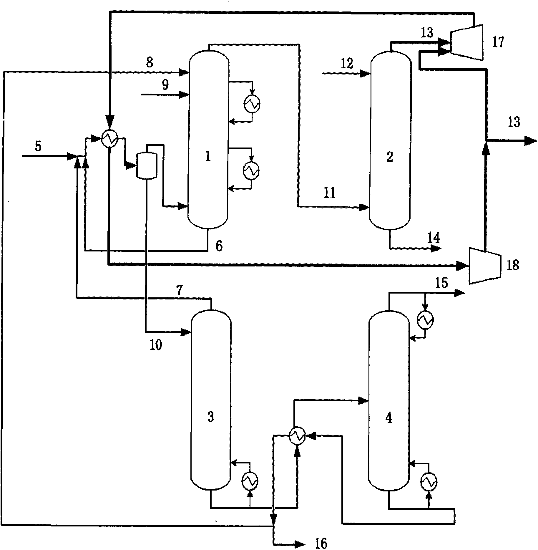
[0019] A refinery with a catalytic processing capacity of 650,000 tons per year is used for simulation, the compressed rich gas capacity is 14241 kg / h, and the naphtha flow rate is 23545 kg / h. This process adopts the desorption tower cold feed process. The compressed rich gas from the catalytic cracking main fractionation tower, the rich absorption oil and the stripped gas from the top of the stripping tower are mixed at about 62°C. The dry gas at the top of the reabsorption tower first passes through the expander until the outlet pressure is 200kpa, and the temperature drops to -38.9°C, and then exchanges heat with the mixture of compressed rich gas, rich absorption oil and desorbed gas, and the mixture is 30.2 after heat exchange ℃, the temperature of the dry gas rises to 25.2°C, and then compressed by the compressor to a pressure of 1500kpa, part of it is discharged from the system as a product, and the rest is recycled back to the inlet of the expander, with a circulation ...

Embodiment 2

[0029] A refinery with a catalytic processing capacity of 650,000 tons per year is used for simulation, the compressed rich gas capacity is 14241 kg / h, and the naphtha flow rate is 23545 kg / h. This process adopts the desorption tower cold feed process. The compressed rich gas from the catalytic cracking main fractionation tower, the rich absorption oil and the stripped gas from the top of the stripping tower are mixed at about 62°C. The dry gas at the top of the reabsorption tower first passes through the expander until the outlet pressure is 250kpa, and the temperature drops to -30.7°C, and then exchanges heat with the mixture of compressed rich gas, rich absorption oil and desorbed gas, and the mixture is 32.5 after heat exchange ℃, the temperature of the dry gas rises to 27.5°C, and then compressed by the compressor to a pressure of 1500kpa, part of it is discharged from the system as a product, and the rest is recycled back to the inlet of the expander with a circulation r...

Embodiment 3

[0040] A refinery with a catalytic processing capacity of 650,000 tons per year is used for simulation, the compressed rich gas capacity is 14241 kg / h, and the naphtha flow rate is 23545 kg / h. This process adopts the desorption tower cold feed process. The compressed rich gas from the catalytic cracking main fractionation tower, the rich absorption oil and the stripped gas from the top of the stripping tower are mixed at about 62°C. The dry gas at the top of the reabsorption tower first passes through the expander until the outlet pressure is 300kpa, and the temperature drops to -23.7°C, and then exchanges heat with the mixture of compressed rich gas, rich absorption oil and desorbed gas, and the mixture is 34.5 after heat exchange ℃, the dry gas temperature rises to 29.5°C, and then compressed by the compressor to a pressure of 1500kpa, part of it is discharged from the system as a product, and the rest is recycled back to the inlet of the expander, with a circulation rate of...


PUM


Abstract

The invention discloses a method for improving yield of liquefied gas by a downstream separation system of a catalytic cracking device. The method comprises the following steps: (1) firstly, expanding dry gas at the tower top of a re-absorption tower through an expander; (2) exchanging heat between the expanded dry gas and a mixture mixing compressed rich gas, rich absorption oil taken out from the tower bottom of an absorption tower and desorbed gas taken out from the tower top of a desorption tower in a heat exchanger, feeding the heat-exchanged mixture into a balance tank, feeding a gas phase obtained in the balance tank as a feeding material to the bottom of the absorption tower, and feeding a liquid phase as a cooling material to the top of the desorption tower; and (3) compressing the heat-exchanged dry gas in step (2) to the pressure of the dry gas at the tower top of the prior absorption tower through a compressor, discharging a part of the compressed dry gas as a product to the system, and circulating the residual part to an inlet of the expander. The method solves the problem of an internal cold source of the system by improving the process flow of the absorbing and stabilizing system, reduces the content of C3 and C4 components in the dry gas, and improves the yield of the liquefied gas.

Description

technical field [0001] The invention relates to a catalytic cracking system in petroleum refining, in particular to a method for increasing the yield of liquefied gas in a downstream separation system of a catalytic cracking device. Background technique [0002] Catalytic cracking is one of the main refining units, and its role is to lighten heavy oil to produce liquefied gas, gasoline and diesel. The absorption and stabilization unit is a downstream separation system in the catalytic cracking unit, which separates the crude gasoline and rich gas from the top of the catalytic fractionation tower into liquefied gas and stable gasoline, and at the same time obtains dry gas as a by-product. The product quality and energy consumption of the absorption stabilization unit have a very important impact on the economic benefits of the entire catalytic cracking unit. [0003] The absorption / desorption process of the absorption stabilization device in my country in the 1960s is a sing...

Claims


Application Information

Patent Timeline
Patent Type & Authority Applications(China)
IPC IPC(8): C10G70/04C10L3/12
Inventor 孙津生王艳红高红梅岚田玉峰
Owner 苏州盛泽科技创业园发展有限公司
Why Eureka
Try Eureka