
Robot MIG welding binocular vision sensing system

A binocular vision and sensing system technology, applied in the field of robot MIG welding binocular vision sensing system, can solve the problems of fixed shooting angle, few passive visual sensing systems, inability to flexibly adjust camera shooting angle images, etc., to reduce Unnecessary collision, enhanced versatility, and reduced bearing pressure

Inactive Publication Date: 2010-11-03
SHANGHAI JIAO TONG UNIV
View PDF2 Cites 0 Cited by
  • Summary
  • Abstract
  • Description
  • Claims
  • Application Information

AI Technical Summary

Problems solved by technology

In addition, because MIG welding (inert gas shielded metal arc welding) has the characteristics of stable arc combustion and good welding quality, it is widely used in the welding of low-alloy thin steel plates. However, the MIG welding process is accompanied by droplet transfer and spatter interference. It makes it difficult to complete weld seam tracking and collect satisfactory molten pool images in real time, so designing a suitable passive vision sensor for robotic MIG welding is of great significance for real-time control of the welding process and assurance of welding quality
[0003] After searching the literature of the prior art, it is found that there are many designs and researches on multifunctional passive vision sensing systems for TIG welding of different materials, while there are few passive vision sensing systems for MIG welding, for example, Chinese patent Application number: 200410067328.1, named "Welding robot servo binocular vision sensor", which realizes that the CCD camera can rotate around the welding gun at a controllable angle to maintain a good image-taking orientation and automatically load or remove the filter and light reduction film The functions include: servo motor, synchronous belt transmission system, two CCD cameras, pneumatic system, light reduction and filter system, two hollow shafts inside and outside, end cover and flat bracket, channel steel bracket and two bearings, The image information of the weld seam and the molten pool can be collected in real time, but the CCD camera uses a fixed focal length lens, and the shooting angle is fixed, so it is impossible to flexibly adjust the camera shooting angle to obtain a better image
Chinese patent application number: 200710037890.3 is a patent titled "Multifunctional Binocular Vision Sensor for Welding Robot and Its Calibration Method". Weld seam starting point guidance, weld seam tracking, and molten pool image acquisition work in real time, but the relative positions of the front and rear eyes of the binocular system are still fixed, and the effect of simultaneously realizing weld seam tracking and molten pool image acquisition during the welding process is not satisfactory. Ideal, it will bring difficulty to the follow-up image processing work
However, there are relatively few studies on molten pool information acquisition and real-time control of MIG welding using passive visual sensing. After literature search, the title is "Robot molten pool visual sensing system for aluminum alloy MIG welding" (Shi Yu et al., Electric Welding Machine, 2006, 27-29, Vol. 36) proposed a set of molten pool visual sensing system, which consists of camera, lens, light reduction filter system, optical path system, etc. pool image acquisition task, but did not clearly propose the specific mechanical structure of the sensing system according to the specific test environment
[0004] After further technical literature search, there is no patent on the vision sensor system applied to robot MIG welding

Method used


Image

  • Robot MIG welding binocular vision sensing system
  • Robot MIG welding binocular vision sensing system
  • Robot MIG welding binocular vision sensing system

Examples


Embodiment Construction

[0023] The embodiments of the present invention are described in detail below. This embodiment is implemented on the premise of the technical solution of the present invention, and detailed implementation methods and specific operating procedures are provided, but the protection scope of the present invention is not limited to the following implementation example.

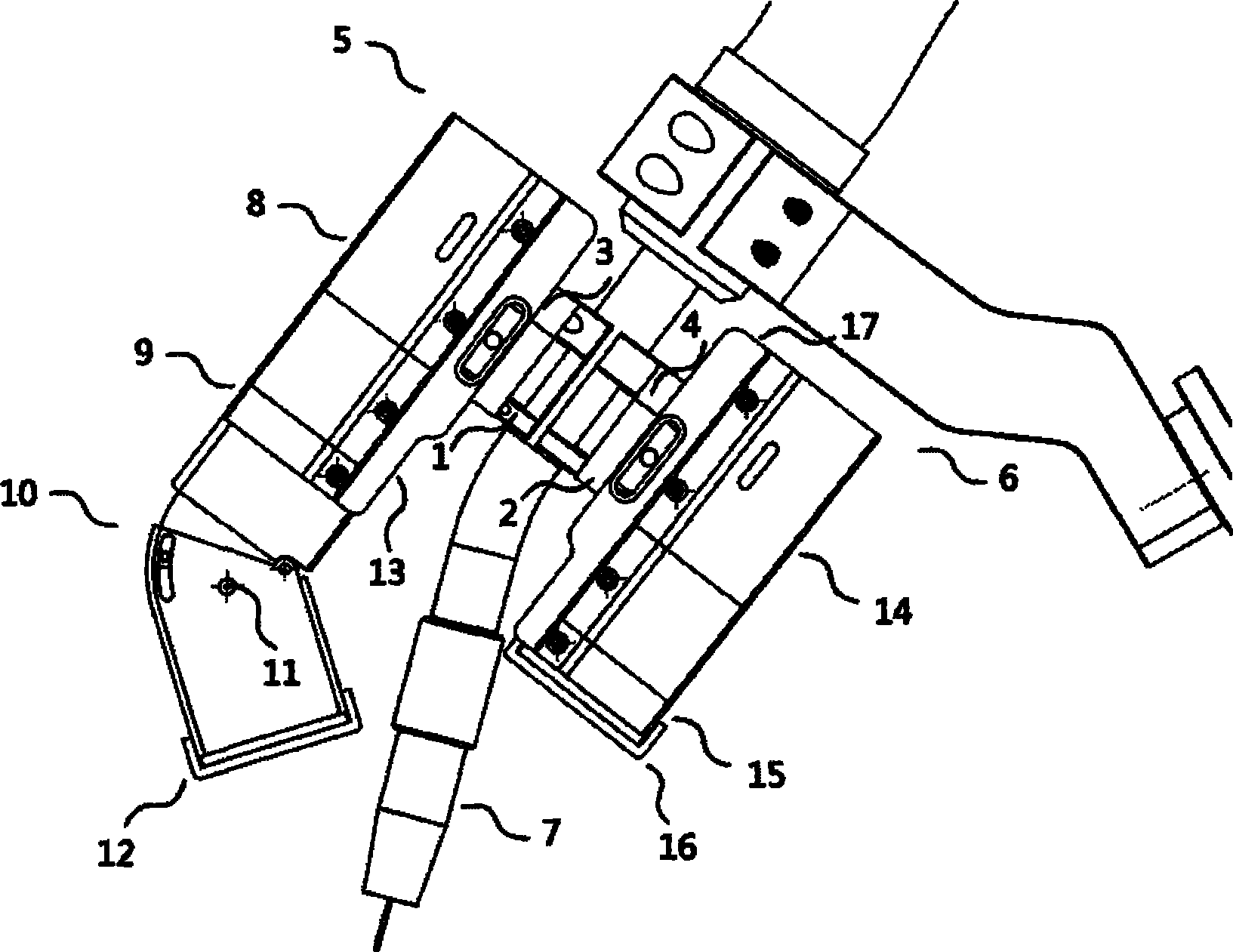
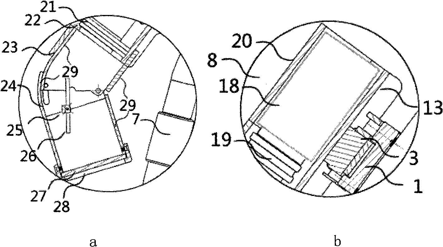
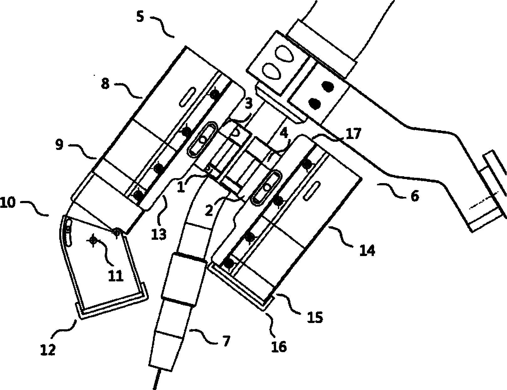
[0024] Such as figure 1 As shown, this embodiment includes: a first welding torch fixing sleeve 1, a second welding torch fixing sleeve 2, a first sensor sleeve connection block 3, a second sensor sleeve connection block 4, a molten pool observation module 5 and a welding seam Tracking module 6, wherein: molten pool observation module 5 and weld seam tracking module 6 are respectively fixed in the first welding torch fixing sleeve 1 and the second welding torch fixing sleeve 2 and are respectively connected with the first sensor sleeve connecting block 3 and the second The sensor sleeve connection blocks 4 are con...


PUM


Abstract

A robot MIG welding binocular vision sensing system in the technical field of automated welding equipment comprises two welding torch fixed sleeves, two sensor sleeve connection blocks, a furnace hearth observation module and a seam tracking module; wherein the furnace hearth observation module and the seam tracking module are respectively fixed on the respective welding torch fixed sleeve and are respectively connected with the two sensor sleeve connection blocks, the sensor sleeve connection blocks are arranged on the welding torch fixed sleeves in a rotary way, and the welding torch fixed sleeves are fixedly connected with an MIG welding torch. The invention obtains clear images by adjusting the angle between a sensor main module and the welding torch as well as the angle between a reflector assembly and the sensor main module, and ensures the welding quality by weld penetration control.

Description

technical field [0001] The invention relates to a device in the field of welding technology, in particular to a robot MIG welding binocular vision sensing system. Background technique [0002] There are more and more automation elements in the modern production process. Automated intelligent welding technology is widely used in industries such as automobiles and shipbuilding. Sensors are important components of robot intelligent welding systems. There are many sensing methods for robot welding, including the first The first generation of contact sensors, the second generation of sensors composed of discrete signal receiving elements, the third generation of sensors composed of highly integrated signal receiving elements, among them, the passive vision sensor with CCD area array as the core has a simple structure, non-contact , large amount of collected information, fast, high-precision and other advantages, can be used for welding initial position guidance, seam tracking and...

Claims


Application Information

Patent Timeline
Patent Type & Authority Patents(China)
IPC IPC(8): B25J19/04B23K9/16B23K9/127G02B7/00G02B7/182G03B29/00
Inventor 严浩叶震卫善春林涛陈善本
Owner SHANGHAI JIAO TONG UNIV
Learn More