Exhaust gas catalysts and exhaust-gas catalytic converter

A technology of catalysts and catalyst carriers, applied in physical/chemical process catalysts, metal/metal oxide/metal hydroxide catalysts, chemical instruments and methods, etc.

Inactive Publication Date: 2010-01-27
大连华昌隆减排技术有限公司
View PDF3 Cites 4 Cited by
  • Summary
  • Abstract
  • Description
  • Claims
  • Application Information

AI Technical Summary

Problems solved by technology

U.S. Patent US20080045405 discloses a catalytic oxidation technology of carbon monoxide and hydrocarbons for diesel engines. This patent also only solves the problem of remo...

Method used


Image

  • Exhaust gas catalysts and exhaust-gas catalytic converter
  • Exhaust gas catalysts and exhaust-gas catalytic converter
  • Exhaust gas catalysts and exhaust-gas catalytic converter

Examples


Embodiment 1

[0054] Take 28g (gram) tungsten silicate (SiO 2 -12WO 3 ) and 55g amine molybdate (NH 4 ) 6 Mo 7 o 24 Dissolve in 1500 ml of deionized water to obtain a slurry, and then heat the slurry to 40°C to 60°C in a water bath, and keep stirring the slurry during heating to completely dissolve the tungsten silicate and amine molybdate to obtain a solution.

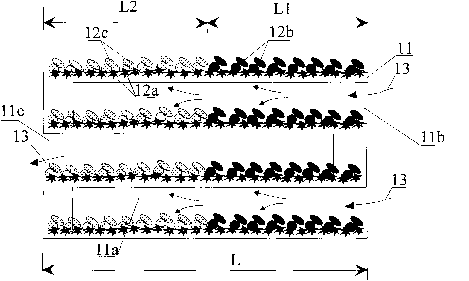
[0055] Take the wall-flow honeycomb cordierite catalyst carrier and dry it at 120°C for 2 hours at a constant temperature. The diameter of the catalyst carrier is 5cm, the length is 6cm, and the porosity of the catalyst carrier is selected as 60%. solution, and the catalyst support was immersed in the solution for 10 minutes. The impregnated catalyst carrier was dried at 120° C. under an air atmosphere for 7 hours, and then the dried catalyst carrier was calcined in an electric heating furnace at 650° C. for 5 hours under an air atmosphere to obtain the first layer of catalyst on the catalyst carrier.

Embodiment 2

[0057] Get 100g potassium nitrate (KNO3) and 92g cobalt nitrate (Co(NO 3 ) 2 ) was dissolved in 1500 ml of deionized water to obtain a slurry, which was heated to 40°C to 60°C in a water bath, and the slurry was continuously stirred until potassium nitrate and cobalt nitrate were completely dissolved to obtain a solution. According to the water absorption of the wall-flow honeycomb ceramic carrier, measure 1 / 2 of the water absorption from the above solution, and immerse the outlet end of the catalyst carrier with the first layer of catalytic layer in Example 1 into the solution , the impregnation time was 5 minutes, the impregnated carrier was dried in air at 120°C for 6 hours, and then placed in an electric heating furnace for sintering and calcining in air at 650°C for 6 hours to obtain the second layer of catalyst at the outlet section of the catalyst carrier.

Embodiment 3

[0059] With 66g praseodymium nitrate (Pr(NO3) 3 ), 136g zirconium nitrate Zr (NO 3 ) 4 , 10 milliliters of 11wt% palladium nitrate (Pd(NO3) 2 ) solution was added into 1500 ml of deionized water to obtain a slurry, the slurry was heated to 40° C. to 60° C., and the slurry was continuously stirred until a completely dissolved solution was obtained. According to the water absorption of the wall-flow honeycomb ceramic carrier, measure 1 / 2 of the water absorption from the solution, and immerse the inlet end of the carrier with the first catalytic layer prepared in Example 1 in the solution. The impregnated catalyst carrier was dried in air at 120° C. for 6 hours for 5 minutes, and calcined in an air atmosphere of 600° C. for 6 hours to obtain the second layer of catalyst on the inlet section of the catalyst carrier.


PUM


Abstract

The invention discloses a catalyst for purifying engine exhaust gas, comprising a catalyst carrier, a first catalyst carrying layer formed on the catalyst carrier, and a second catalyst carrying layer formed on the first catalyst carrying layer, wherein the first catalyst carrying layer comprises a first catalyst component which comprises a tungsten oxide and one of the molybdenum oxide, technetium oxide or ruthenium oxide; the second catalyst carrying layer comprises a near-end catalyst carrying layer and a far-end catalyst carrying layer which are connected; the near-end catalyst carrying layer comprises a second catalyst component which comprises a palladium oxide and one of praseodymium oxide, lanthanum oxide or rubidium oxide; and the far-end catalyst carrying layer comprises the mixed oxide of alkali metals and transition metals. The experimental result shows that the catalyst can remove carbon monoxide, hydrocarbon and particulate matters from the exhaust gas of a diesel engine synchronously in a same catalytic converter at a lower temperature.

Description

technical field [0001] The invention relates to the field of tail gas treatment, in particular to an tail gas catalyst and a tail gas catalytic converter for treating diesel engine tail gas. Background technique [0002] With the rapid development of the automobile industry, the tail gas emitted by internal combustion engines has become one of the main pollution sources of the atmosphere. For example, the tail gas emitted by diesel engines contains carbon monoxide (CO), hydrocarbons (HC), nitrogen oxides and particulate matter (PM, Composed of dry soot, liquid hydrocarbons and a small amount of sulfate) and other substances that are extremely harmful to the human body and the public environment. In order to eliminate the severe pollution caused by diesel engine exhaust, countries around the world have enacted more stringent emission regulations. With the implementation of these emission regulations, diesel engines must improve their design to reduce emission levels. Even so...

Claims


Application Information

Patent Timeline
IPC IPC(8): B01J23/30B01J23/28B01J23/78B01J23/63B01J21/06B01D53/94B01D53/62B01D53/72F01N3/28
CPCY02A50/20
Inventor 任雪华
Owner 大连华昌隆减排技术有限公司
Why Eureka
Try Eureka