Process for producing magnetic element
A magnetic device and magnetic film technology, which is applied in the field of manufacturing magnetic devices, can solve problems such as poor reactivity of magnetic materials, and achieve the effects of improved yield and high etching rate
- Summary
- Abstract
- Description
- Claims
- Application Information
AI Technical Summary
Problems solved by technology
Method used
Image
Examples
Embodiment 1
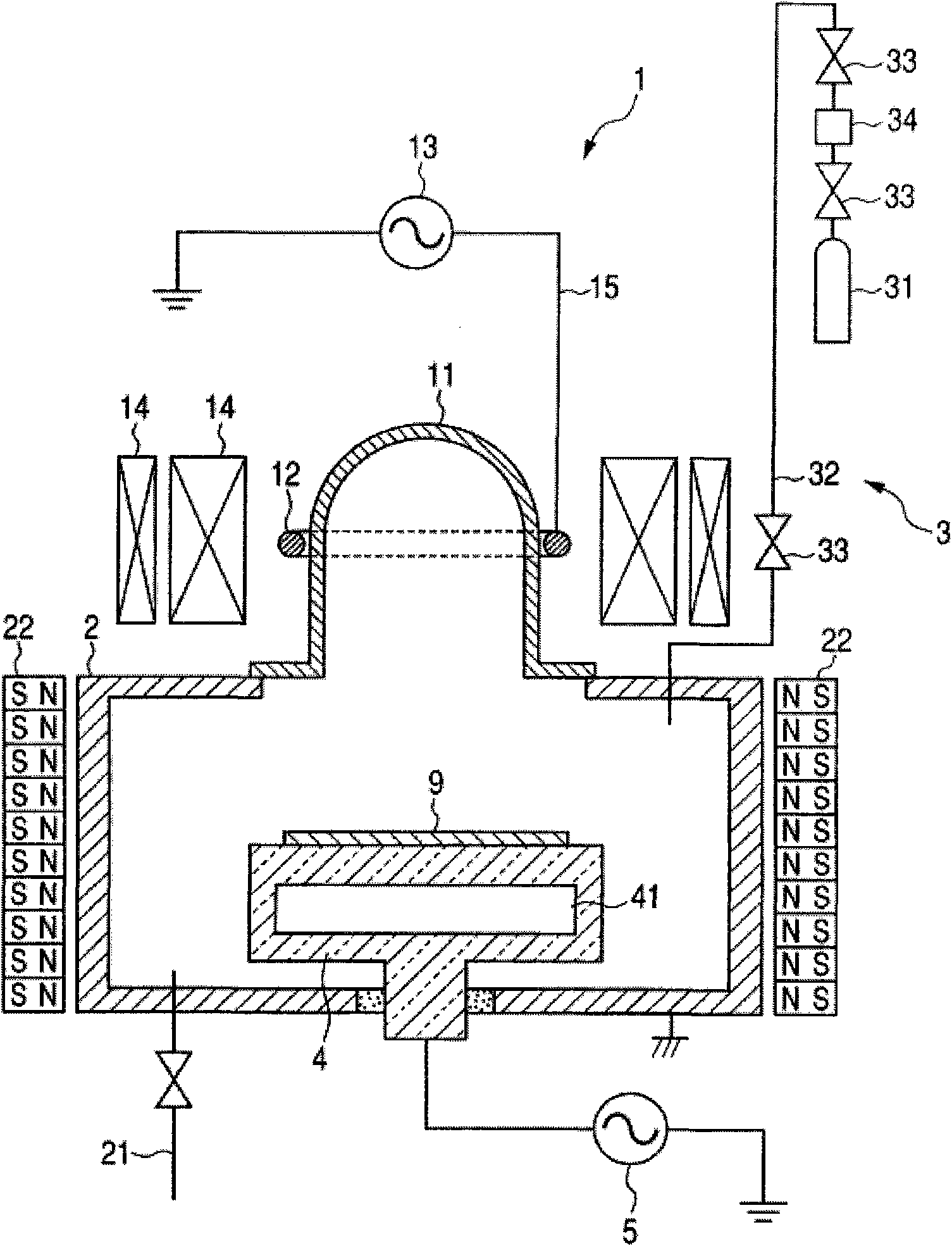
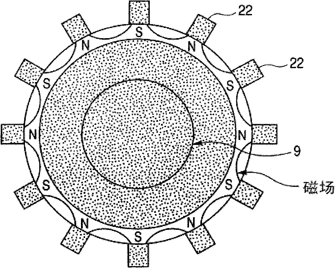
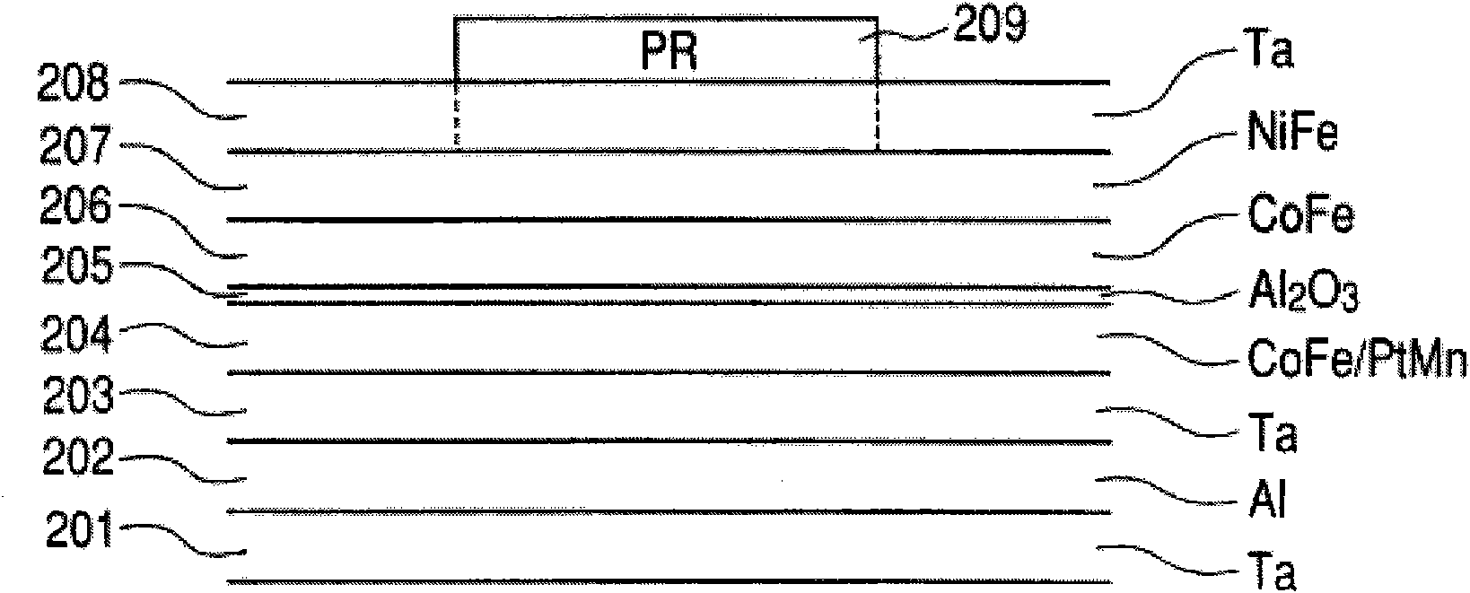
[0036]FIG. 1 is a schematic diagram of an etching apparatus with an ICP (Inductively Coupled Plasma) plasma source. In Example 1, acetic acid was used as a vaporizing compound, a mixed gas of acetic acid and oxygen was used as an etching gas, and by using the apparatus shown in FIG. 1, as Figure 2A and Figure 2B Etched TMR elements are shown. Figure 2C and image 3 Two examples of TMRs manufactured using the manufacturing method according to the present invention are shown. Figure 2A The laminated structure before the etching process used in the present invention is shown. it is Figure 1A A wafer 9 shown in , in which a magnetic material layer and the like are laminated on a substrate composed of quartz or the like, is an object of etching.
[0037] exist Figure 2A Among them, 201 refers to a Ta film, 202 refers to an Al film, 203 refers to a Ta film, and 204 refers to a laminated ferromagnetic film, which is composed of a soft magnetic CoFe film with a thickness of...
Embodiment 2 to 20 and comparative example 1
[0058] In the same manner as in Example 1, except that the etching gas shown in Table 2 was used instead of the etching gas composed of acetic acid gas and oxygen gas used in the above-mentioned Example 1, the etching gas shown in Table 2 was formed. Figure 2C In the element, the etch rate and selectivity were measured. The results are shown in Table 1 below. The etching rates shown in Table 1 are shown as ratios when the etching rate in Example 1 is "1" and the selectivity is "1".
[0059] Table 1
[0060] Example
[0061] As described above, the dry etching method used in the manufacturing method according to the present invention exhibits unexpectedly remarkable effects.
Embodiment 21 to 25 and comparative example 2
[0063] In the same manner as in Examples 1, 9, 3, 6, and 13 except for changing the flow rate of the etching gas in the above-mentioned examples, the Figure 2C Components in , and measure the etch rate and selectivity ratio. The results are shown in Table 2. The etching rates shown in Table 2 are shown as ratios when the etching rate in Example 1 is "1" and the selectivity is "1".
[0064] Table 2
[0065] Example
[0066] Among ethers, aldehydes, carboxylic acids, diketones, and amines, ethers and aldehydes are not corrosive, and the safety is particularly favorable.
PUM
| Property | Measurement | Unit |
|---|---|---|
| thickness | aaaaa | aaaaa |
| thickness | aaaaa | aaaaa |
| thickness | aaaaa | aaaaa |
Abstract
Description
Claims
Application Information
 - R&D
- Intellectual Property
- Life Sciences
- Materials
- Tech Scout
- Unparalleled Data Quality
- Higher Quality Content
- 60% Fewer Hallucinations
Browse by: Latest US Patents, China's latest patents, Technical Efficacy Thesaurus, Application Domain, Technology Topic, Popular Technical Reports.
© 2025 PatSnap. All rights reserved.Legal|Privacy policy|Modern Slavery Act Transparency Statement|Sitemap|About US| Contact US: help@patsnap.com


