Multi-stage heat-exchange and waste heat recovery hot-air system with function of purifying fuel gas

A flue gas purification and waste heat recovery technology, which is applied in air heaters, indirect heat exchangers, fluid heaters, etc., can solve problems such as single function, unsatisfactory effect, and recovery temperature that cannot be consistent with hot air temperature. Waste heat recovery, convenient flue gas purification, and large heat capacity

Inactive Publication Date: 2010-02-17
肖建选
View PDF0 Cites 10 Cited by
  • Summary
  • Abstract
  • Description
  • Claims
  • Application Information

AI Technical Summary

Problems solved by technology

Some other hot air systems are equipped with waste heat recovery devices on their flues to reduce heat energy waste, but because the recovery temperature cannot be consistent with the hot air temperature, that is, they cannot be used directly with the hot air generated by the primary heating of the above-mentioned hot air stove - the function is single and the effect not ideal
[0004] In addition, from the perspective of environmental protection, today's soot purification equipment is independent of hot blast stoves (or boilers) and waste heat recovery devices. recycle and re-use

Method used


Image

  • Multi-stage heat-exchange and waste heat recovery hot-air system with function of purifying fuel gas
  • Multi-stage heat-exchange and waste heat recovery hot-air system with function of purifying fuel gas
  • Multi-stage heat-exchange and waste heat recovery hot-air system with function of purifying fuel gas

Examples


example 1

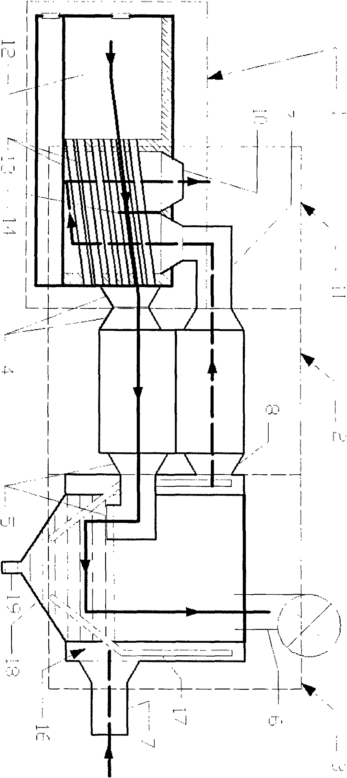
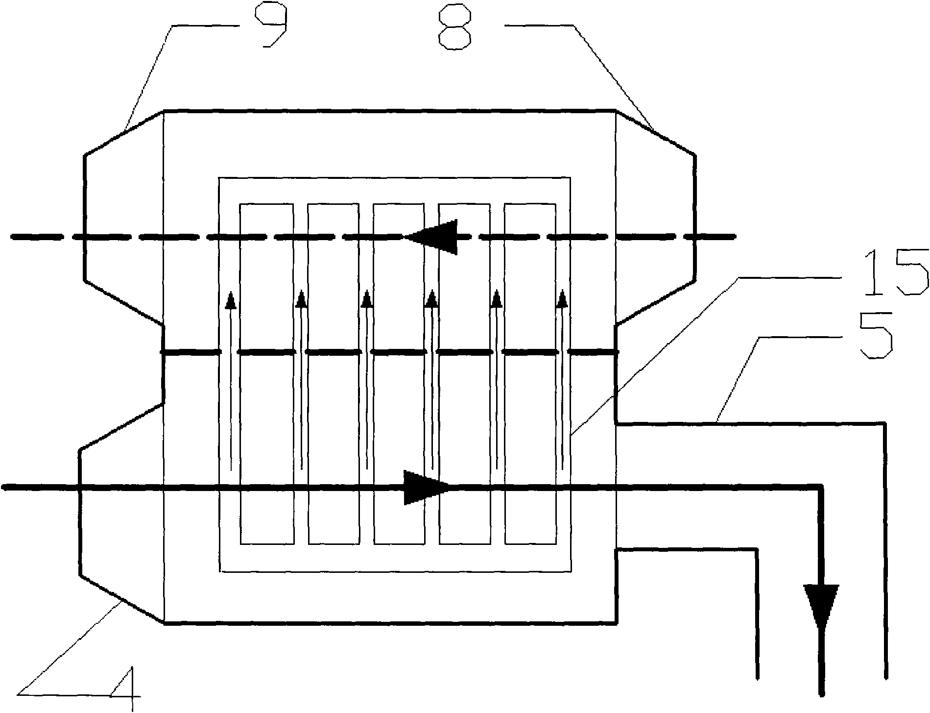
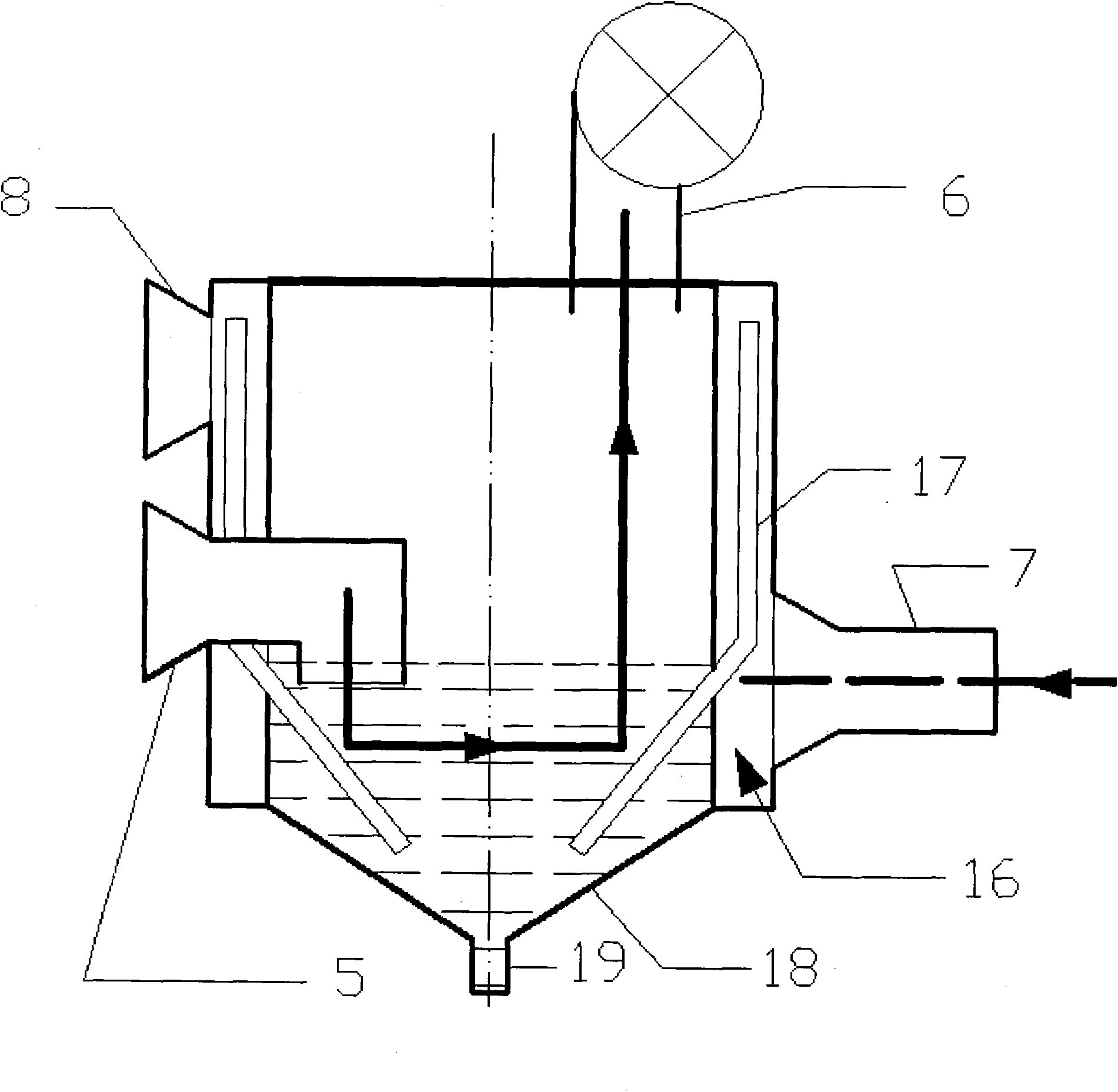
[0032] The multi-stage heat exchange-waste heat recovery hot blast system with flue gas purification function is mainly composed of a hot blast stove (1) including a furnace heat exchanger (11), an external heat exchanger (2) and a waste heat recovery device (3) in series. It also includes accessories such as connections, insulation and piping.

[0033] The hot blast stove (1) mainly includes a combustion chamber (12) and a heat exchanger (11) in the furnace, which are separated by a fire wall made of refractory bricks or filled with insulating materials to form a heat insulating fire wall. The heat exchange fire pipe (13) is inserted inside the heater (11). The heat exchange fire tube is connected to the combustion chamber (12) and the primary flue (4). In order to fully exchange heat between the hot air and the flue gas in the heat exchange fire tube (13), one or more diversion walls (14) are arranged in the heat exchanger (11) in the furnace, the effect is to make the hot ...

example 2

[0050] For the connection of the above three major components and their respective parts, if possible, processes other than welding are also used, and the components are flanged or directly socketed.


PUM


Abstract

The invention relates to a multi-stage heat-exchange and waste heat recovery hot-air system with the function of purifying fuel gas, which is mainly and organically formed by three components including a hot-air furnace containing a heat exchanger inside the furnace, a heat exchanger outside the furnace and a waste heat recoverer. The three components make full use of the heat energy generated bythe hot-air furnace in the modes of heating the air at a high temperature, a medium temperature and a low temperature, and the heat efficiency is much higher than that of a single-stage heat exchangerhot-air furnace and a hot-air furnace without waste heat recovery. Furthermore, the waste heat recovery of the last stage adopts smoke-water-gas secondary heat exchange, and the functions of fuel gaspurification, desulfuration and denitrification and the almost complete purification can be achieved on the basis of the existing function of dust removal by adding a purification drug in to an intermediate and water. The integral design of the multi-stage heat-exchange and waste heat recovery hot-air system with the function of purifying fuel gas has the advantages that the system can be optimized and the effect of not influencing the realization of other functions while various devices realize the functions thereof can be achieved.

Description

technical field [0001] The invention relates to a hot air system, in particular to a hot air system which performs multi-stage heat exchange-waste heat recovery and has the function of purifying flue gas. Background technique [0002] In the industrial field, there are many places that need to use hot air for drying, heating, baking and other processes, and the most direct way to generate hot air is the hot air stove. The coal-fired hot air stove is the most commonly used in my country. It has the characteristics of simple structure, low cost, frequent maintenance and short life. Due to coal combustion, the operating cost is the lowest but also the most polluting. Under the situation of "energy saving and emission reduction" It is restricted in use. [0003] The common hot air system is a simple combination of a low-cost hot air stove and a blower. The heat energy generated by fuel combustion is transferred to the air through the partition wall at one time to form hot air. I...

Claims


Application Information

Patent Timeline
Patent Type & Authority Applications(China)
IPC IPC(8): F24H3/00F28D15/02B01D47/02
CPCY02P70/10
Inventor 肖建选
Owner 肖建选
Why Eureka
Try Eureka