
Method for separating and processing marine oily water and processing device thereof

A separation treatment and treatment device technology, applied in water treatment devices, ship parts, ship construction, etc., can solve problems such as high viscosity, separation membrane pollution, incomplete separation, etc., and achieve the effect of saving cabin space and increasing coverage area

Inactive Publication Date: 2010-11-17
DONGTAI CITY DONGFANG MARINE FITTING
View PDF0 Cites 0 Cited by
  • Summary
  • Abstract
  • Description
  • Claims
  • Application Information

AI Technical Summary

Problems solved by technology

But the density is 980kg / m 3 The above residual oil itself has a high density, coupled with the existence of some pollutants (such as rust), the oil droplets often absorb some rust, making the density difference between the residual oil and water extremely small, or exceeding the density of water, and its viscosity is very high , making it more difficult to gather and separate oil droplets to float up, and it is even impossible to separate them by traditional gravity methods
Furthermore, because the resolution of MEPC.107(49) increases the requirement of the separation device for the separation of oily water containing emulsified oil, the oil impurities in the emulsified oil are suspended for a long time and evenly distributed in the water, which has a high degree of stability and cannot gather and float , no doubt relying on the traditional gravity separation method is unable to achieve the separation of oily water containing emulsion
[0005] Although people have separated by membrane filtration on the basis of gravity separation plus a mechanical oil droplet polymerizer, theoretically this separation method can achieve the separation of emulsified oil. , the accumulation of the retentate on the surface of the membrane will produce a thin layer of gel layer on the surface of the membrane, which will cause the pollution of the separation membrane. What is more serious is that the separation membrane is usually lipophilic. During the separation process, the previous treatment method cannot Thoroughly separate the oil droplets, solids and water in the oily sewage. During the membrane separation process, the rapid flow of the liquid makes the oil droplets and solid impurities quickly enter the dense pores, causing the internal blockage of the membrane, the pollution of the membrane surface and the membrane pores. The clogging prevents water molecules from passing through the dense pores and entering the other side of the membrane under the action of lateral pressure.
Tests have shown that the membrane flux of the treatment device with this structure will drop significantly in just a few weeks or even a few days, and as time goes on, the membrane flux will generally decrease exponentially. Taking out the separation membrane for cleaning or updating the separation membrane not only significantly increases the operating cost of the separation device, but is also very difficult under the condition of very limited space on the ship
[0006] Due to the limitation of the separation structure and separation method of the gravity separation stage in the existing oily sewage separation treatment device, it can neither separate the residual oily sewage with a higher density, nor can it effectively eliminate the oil droplet components and solids in the oily sewage. Impurities, which increase the burden on the membrane separation stage, cause the membrane separation to fail quickly, and the functions of each separation stage of the separation treatment device are mutually restrained, and they cannot perform their own responsibilities, which eventually leads to the failure of the entire device to work normally.

Method used


Image

  • Method for separating and processing marine oily water and processing device thereof
  • Method for separating and processing marine oily water and processing device thereof
  • Method for separating and processing marine oily water and processing device thereof

Examples


Embodiment Construction

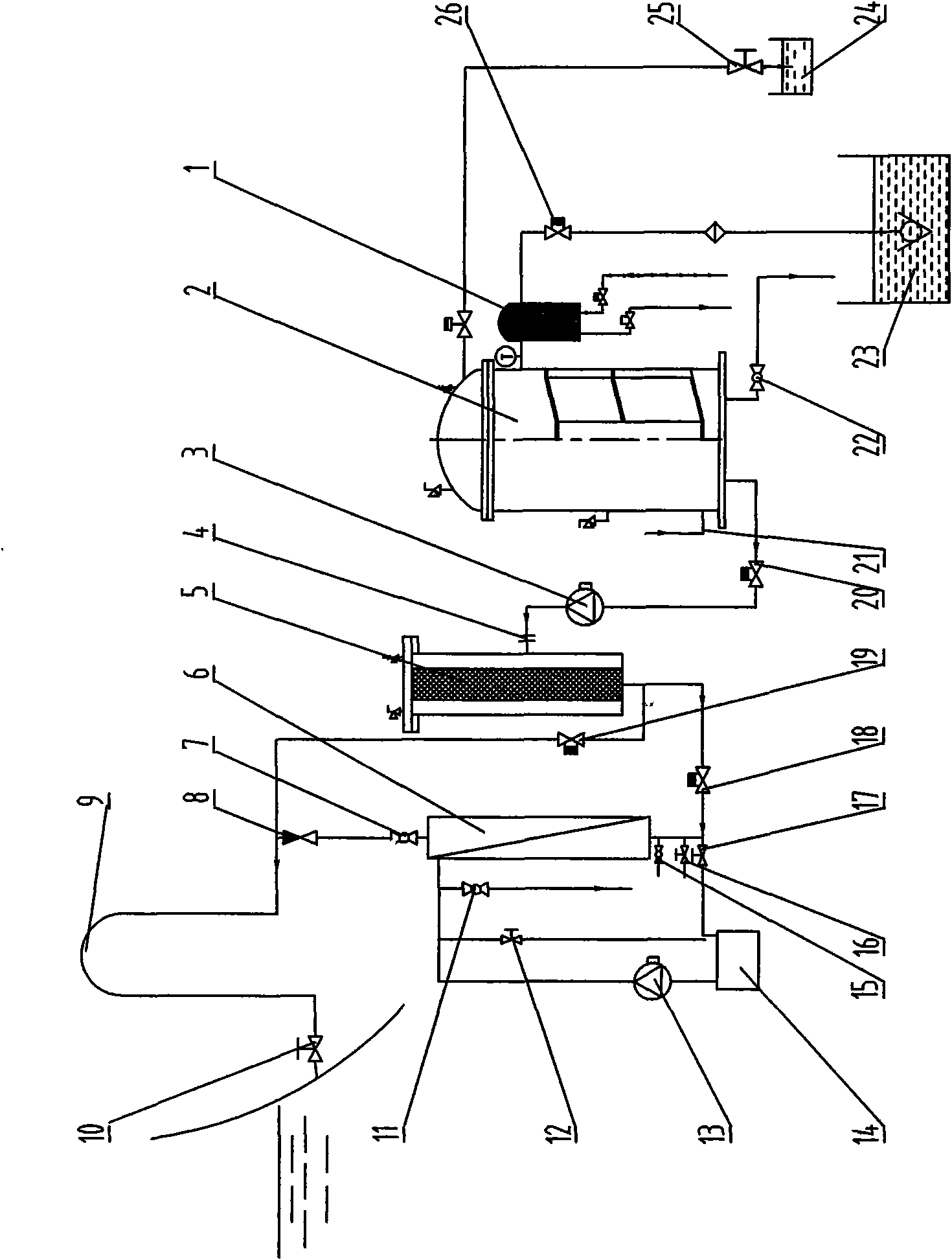
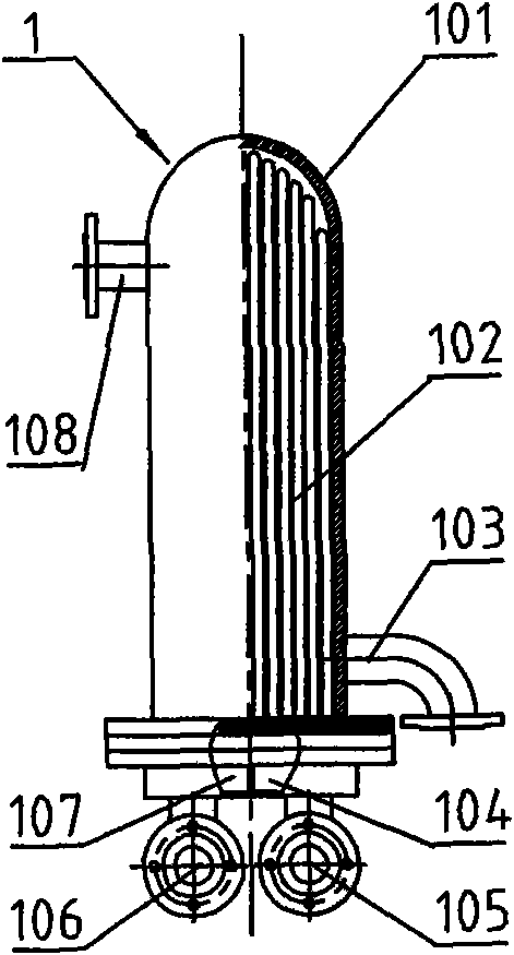
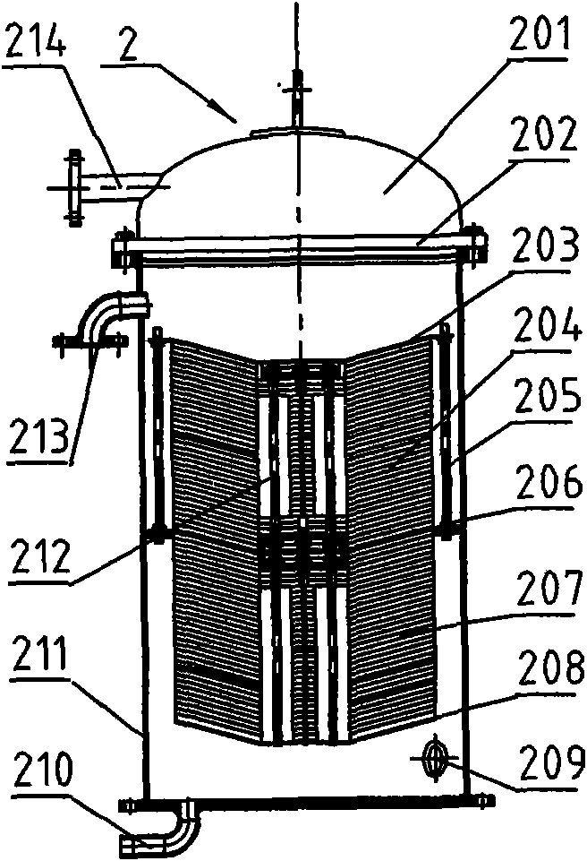
[0037] like figure 1As shown, the marine oily sewage treatment device includes a heater 1, a gravity separator 2, a suction pump 3, a filter material filter 5 and a membrane processor 6 connected in sequence through pipelines; the filtered water outlet of the filter material filter 5 It communicates with the filtered water inlet 608 of the membrane processor 6 and the sea valve 10 connected to each other. Under the action of the suction pump 3, the oily sewage in the bilge oily sewage station 23 enters the heater 1 through the oily sewage input valve 26, and the suction pump 3 adopts a screw pump; The oily sewage is preheated to 48°C to 58°C, preferably the preheating temperature is controlled between 52°C to 56°C. The preheated oily water is continuously sucked into the gravity separator 2. The upper part of the gravity separator 2 is a static separation chamber with a dome-shaped top cover, and the lower part of the cylinder chamber is equipped with a collection separator f...


PUM


Abstract

The invention discloses a method for separating and processing marine oily water and a processing device thereof. The method comprises the following steps: preheating treatment is carried out on bilge oily water to 48-58 DEG C; oil drop aggregation and oil-water gravity separation are carried out to separate out waste oil and separate water; the separated water is filtered into filtered water by a filter-material filter device and then is sent to a separation process device; concentrated solution is recovered; and infiltration water is discharged outside cabin. The device for processing marine oily water of the invention comprises a heater, a gravity separator, a suction pump, a filter-material filter and a membrane processor communicated sequentially; the oily water inlet of the heater is connected to a bilge oily water station; and the infiltration water outlet of the membrane processor is communicated with a sea valve by a puff pipe. The invention not only can realize separation process of high-density residuum oily water, but also can realize effective separation process of emulsion in oily water, so as to meet strict emission standard, thereby being widely used in separation process of bilge oily water.

Description

technical field [0001] The invention relates to the technical field of oily sewage treatment, in particular to a separation and treatment method for marine bilge oily sewage. The invention also relates to an oily sewage treatment device adopting the oily sewage separation treatment method. Background technique [0002] With the rapid development of the world's shipping industry and the rapid increase of ship tonnage, the improper discharge of ship bilge oily sewage has become the most important form of marine pollution caused by ships. After the ship's oily sewage is discharged into the ocean water body, a very thin layer of oil film is formed on the surface of the water body. According to data analysis, 1 ton of oil product is discharged to the water surface to form a 5×10 6 m 2 This kind of oil film directly hinders the transfer of oxygen in the atmosphere to the water body, making the water body anoxic, and aquatic organisms die due to lack of oxygen; the oil product is...

Claims


Application Information

Patent Timeline
Patent Type & Authority Patents(China)
IPC IPC(8): B63J4/00
CPCB63J4/004
Inventor 陈海兵梅冬兴蔡晓幸马如中何丽君
Owner DONGTAI CITY DONGFANG MARINE FITTING
Learn More