Method and device for fluidized catalytic conversion

A fluidized catalysis and catalyst technology, applied in catalytic cracking, cracking, petroleum industry and other directions, can solve the problems of reduced catalyst activity, inability to optimize the operating conditions of the reaction system, and unfavorable catalytic conversion reactions.

Active Publication Date: 2010-03-10
LUOYANG WEIDA PETROCHEMICAL ENG CO LTD
View PDF4 Cites 11 Cited by
  • Summary
  • Abstract
  • Description
  • Claims
  • Application Information

AI Technical Summary

Problems solved by technology

The disadvantage of this technology is that the regenerated agent and the spent agent are directly mixed, which reduces the activity of the catalyst entering the riser reactor, which is not conducive to the catalytic conversion reaction.
[0008] The current heat extraction technology, that is, the catalyst

Method used


Image

  • Method and device for fluidized catalytic conversion
  • Method and device for fluidized catalytic conversion
  • Method and device for fluidized catalytic conversion

Examples


Embodiment 1

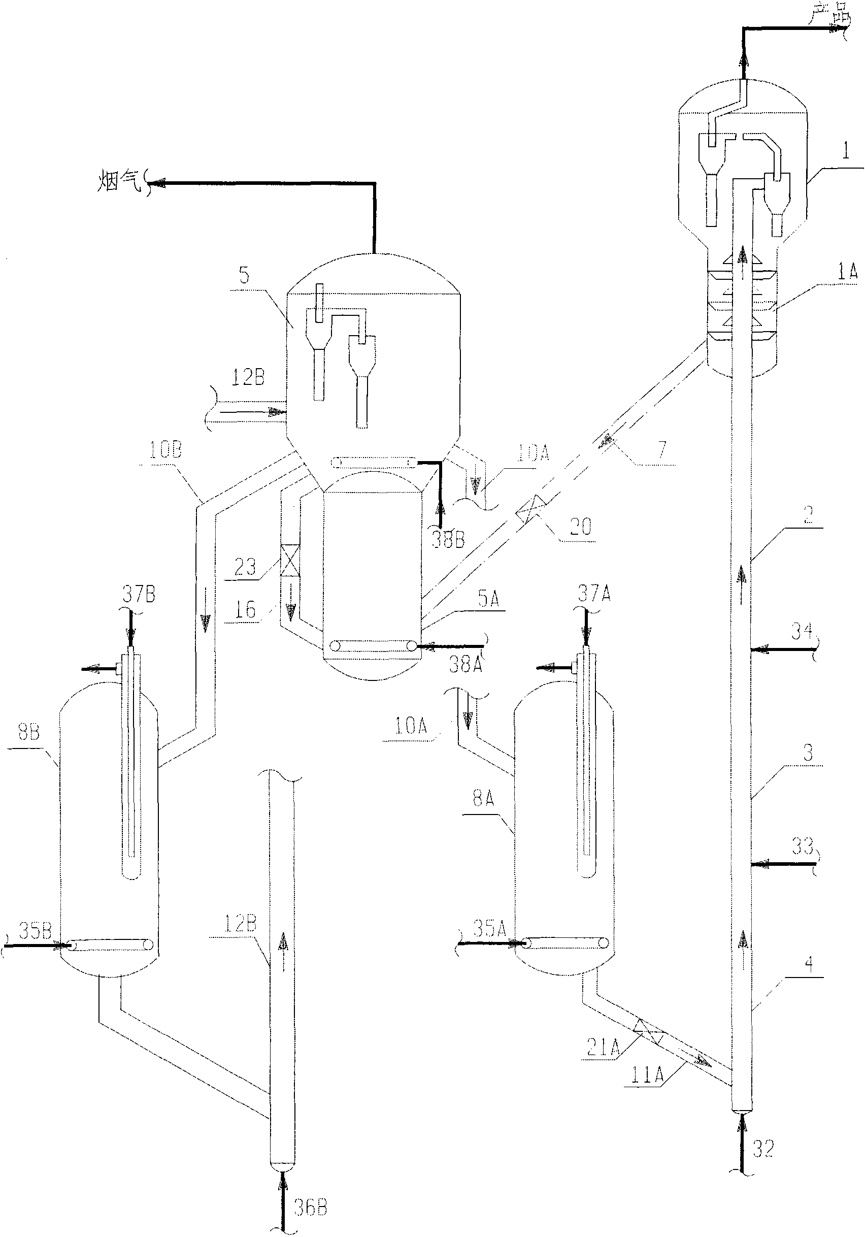
[0172] To verify the effect of the present invention, adopt figure 1 The process flow shown, the process conditions shown in Table 2, the raw materials shown in Table 1, and the CORH catalyst produced by the Changling Refinery Catalyst Plant, and the test results are shown in Table 3.

[0173] In Table 2, Scheme A of the prior art adopts conventional catalytic conversion technology: the temperature of the regenerator catalyst bed is 680°C, and the reaction temperature is 505°C. The raw material temperature is 200°C, and the agent / oil ratio is 6.0. Therefore, the temperature difference between the regenerant and the raw material is 480°C. Solution A of the prior art has the following shortcomings:

[0174] (1) The temperature of the feedstock at 200°C is quite low for the cracking of the residue-containing feedstock.

[0175] (2) Although the temperature of the regenerator meets the regeneration requirements, the temperature is too high when it comes into contact with the raw mater...

Embodiment 2

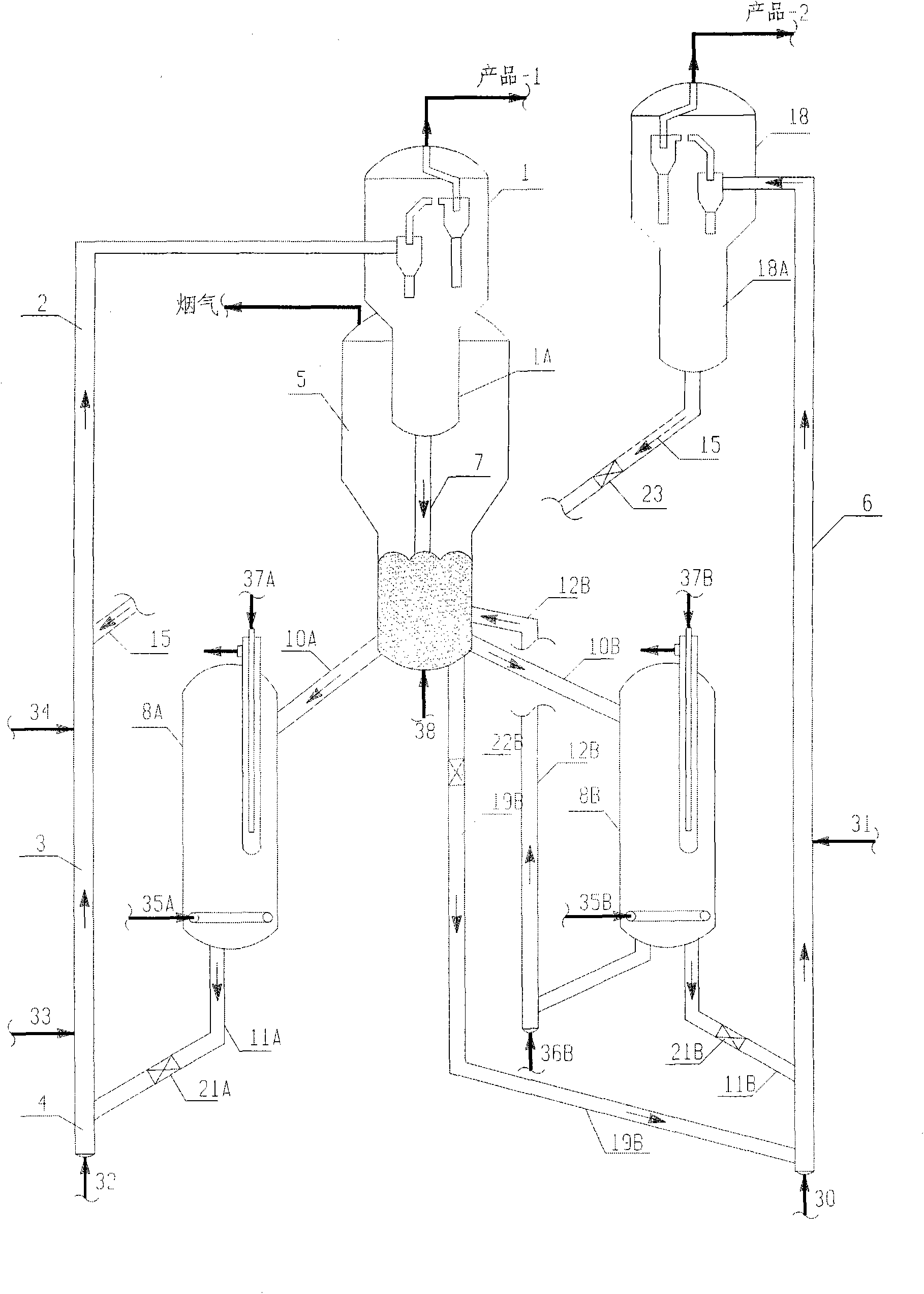
[0185] To verify the effect of the present invention, adopt figure 2 In the process flow shown, the heavy oil riser adopts the process conditions shown in Table 2, the raw materials shown in Table 1, and the CORH catalyst produced by the Changling Refinery Catalyst Plant. The test results are shown in Table 4.

[0186] The results in Table 4 show that the coke and dry gas yield decreased by 2.1%, the olefin volume content in gasoline decreased by 65%, and the octane number (RON) increased by 0.6 units.

[0187] Table 4

[0188]

Product

current technology

Plan A

this invention

Plan B

Product yield Wt%

Fuel gas

5.2

3.7

LPG

14.4

14.1

Petrol

45.6

49.5

Diesel

23.6

25.1

Oil slurry

3

-

Coke

8.2

7.6

Total

100.0

100.0

Gasoline quality

Olefin content V%

37.2

13.6

Aromatic content V%

31.6

37.9

Octane number RON

90.1

90.7

[0189] The raw material of the gasoline riser is catalytically cracked gasoline. The...


PUM


Abstract

The invention provides a method for catalytic conversion of heavy oil, which comprises a fluidized catalytic conversion process that: heavy hydrocarbon raw materials contacts a catalyst in a riser reactor or fluidized bed reactor to react; the reaction temperature is 400 to 650 DEG C (preferably 480 to 560 DEG C); the reaction pressure is 0.11 to 0.4MPa; the contact time is 0.05 to 5 seconds (preferably 0.1 to 3 seconds); and the weight ratio of the catalyst to the raw materials ( catalyst to oil ratio) generally is 3 to 15, preferably 5 to 12. The reaction products flow in a settler for catalyst and oil gas separation; the separated catalyst to be regenerated is stripped by a stripping section and enters a regenerator for coke burning regeneration; and the regenerated catalyst is cooled or directly returns to the riser reactor to be recycled. The method can solve the problems encountered in the resid-blend ratio improvement and gasoline upgrade and update processes of the prior catalytic conversion.

Description

Technical field [0001] The invention belongs to the field of catalytic cracking, and relates to a method and a device for the catalytic conversion of heavy oil. The present invention particularly relates to high density (such as more than 920kg / m 3 ) Method and device for catalytic conversion of naphthenic wax oil. Background technique [0002] As the quality of crude oil is deteriorating and the trend of requalification is increasing, the blending ratio of catalytic conversion residues continues to increase, and the quality of gasoline produced by catalytic conversion, coking, and thermal cracking processes has become worse. On the one hand, olefins in gasoline are effective components with high octane number. On the other hand, they produce more pollutants during the combustion process and pollute the environment. Although the use of traditional hydrorefining can reduce the olefins in gasoline to a very low level, the octane number is greatly lost. In order to solve the above...

Claims


Application Information

Patent Timeline
IPC IPC(8): C10G11/18
Inventor 李群柱李莉
Owner LUOYANG WEIDA PETROCHEMICAL ENG CO LTD
Why Eureka
Try Eureka