Liquid blast furnace slag granulation method and device thereof

A blast furnace slag and granulation technology, which is applied in the field of blast furnace slag utilization, can solve the problems of heavy system maintenance workload, large power consumption, and large system power consumption, and achieve the effects of reducing air consumption, increasing impact force, and strengthening effect

Inactive Publication Date: 2010-03-10
TSINGHUA UNIV +1
View PDF0 Cites 34 Cited by
  • Summary
  • Abstract
  • Description
  • Claims
  • Application Information

AI Technical Summary

Problems solved by technology

[0004] At present, my country's liquid blast furnace slag is mainly quenched by water quenching method. The blast furnace slag after water quenching can be used to make building materials such as cement. The problems of water quenching method are: high water consumption; 2 S and SO x It is discharged into the atmosphere with steam, which promotes the formation of acid rain and pollutes the environment; the sensible heat of blast furnace slag has not been recycled; the water-quenched slag has a high moisture content, and it still needs to be dried as a cement raw material, which requires a certain amount of energy; the system consumes a lot of power; The fine particles contained in the circulating water of water flushing slag will cause serious wear and blockage of pumps and valves and other components, and the system maintenan

Method used


Image

  • Liquid blast furnace slag granulation method and device thereof
  • Liquid blast furnace slag granulation method and device thereof

Examples


Example Embodiment

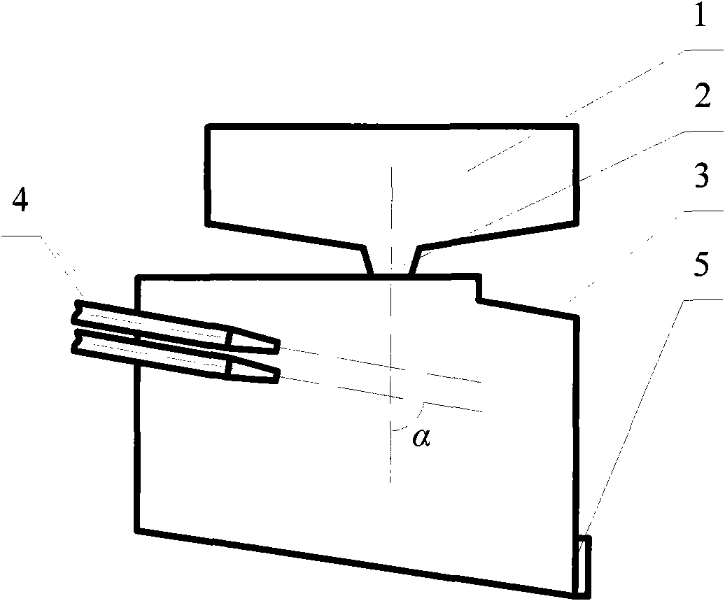
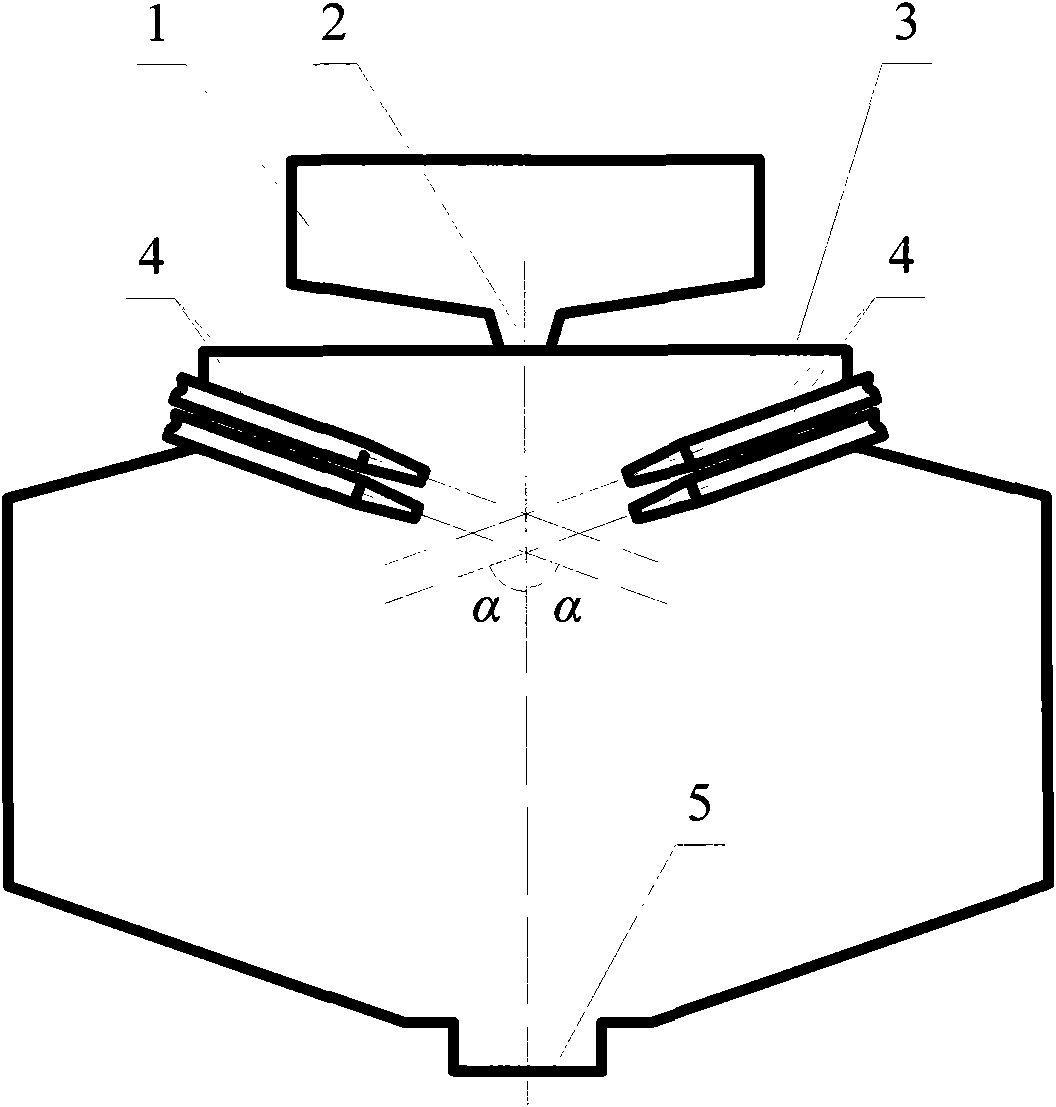
[0017] The specific structure, working principle and implementation manner of the device will be described in detail below with reference to the accompanying drawings.

[0018] The present invention includes a diversion groove 1 , a slag drop port 2 , a dry granulator 3 , a granulation nozzle 4 , and a slag discharge port 5 . The diversion trough 1 is made of refractory materials and is arranged on the top of the granulator. The lowest point of the diversion trough is provided with a slag drop port 2 that communicates with the dry granulator 3. narrow. The liquid blast furnace slag from the blast furnace slag ditch or slag tank flows into the diversion groove 1 , flows out from the slag drop opening 2 at the lower part of the diversion groove 1 and falls vertically into the granulator 3 . The upper part of the granulator 3 is provided with a granulation nozzle 4, and the included angle α between the outlet axis of the granulator nozzle 4 and the vertical direction is 0-90°, s...


PUM


Abstract

The invention relates to liquid blast furnace slag granulation method and device thereof, belonging to the technical field of blast furnace utilization in the metallurgy industry. The device comprisesa diversion trench, a slag dropping hole, a granulation device, two or more granulation nozzles and a slag discharging hole. The invention realizes dry process quenching granulation adopting high-speed gas and solid phases carrying solid granules as granulation media, impacting liquid blast furnace slag to crushing, and quenching and solidifying into small granules. In the granulation device, thediversion trench is built by refractory materials and is arranged at the top of the granulation device, the lowest point of the diversion trench is provided with the slag dropping hole which is communicated with the granulation device, the upper part of the granulation device is provided with the granulation nozzles, and an included angle between the outlet axes and the vertical direction of thegranulation nozzles is more than 0 degree and is less than or equal to 90 degrees. The granulation nozzles can be arranged at one side or are symmetrically arranged or circularly arranged by using a center perpendicular line of the slag dropping hole as the center of a circle. The invention strengthens the granulation effect and lowers the power consumption and the equipment investment of the granulation device by utilizing the capacity of crushing the liquid blast furnace slag by a gas-solid two-phase strong jet flow.

Description

technical field [0001] The invention relates to a liquid blast furnace slag granulation method and a device thereof, belonging to the technical field of blast furnace slag utilization in the metallurgical industry. Background technique [0002] Blast furnace slag is a silicate material with good properties, which can be used as a raw material for the production of building materials and fertilizers. After rapid cooling, liquid blast furnace slag has no time to form mineral crystals and stores part of the chemical energy in the formed glass body, so it has high activity. The blast furnace slag after quenching treatment has potential hydraulic gelling properties and is excellent. Cement raw materials, so quenched blast furnace slag has a huge market demand. [0003] At the same time, the temperature of liquid blast furnace slag is between 1350°C and 1500°C, which belongs to high-grade waste heat resources and has high recycling value. [0004] At present, my country's liquid...

Claims


Application Information

Patent Timeline
IPC IPC(8): C21B3/06
CPCY02W30/50
Inventor 张衍国蒙爱红李清海杜滨
Owner TSINGHUA UNIV
Why Eureka
Try Eureka