
Correlated electron memory

A memory and storage unit technology, applied in static memory, digital memory information, information storage, etc., can solve the problems of no storage window, unsuitable memory, and no resistance conversion memory.

Active Publication Date: 2011-09-28
思美存储器有限公司
View PDF5 Cites 0 Cited by
  • Summary
  • Abstract
  • Description
  • Claims
  • Application Information

AI Technical Summary

Problems solved by technology

However, no working resistive switching memory has ever been made because no one knew how to make thin-film resistive switching materials that are stable over time and temperature.
Furthermore, all resistive switching mechanisms proposed so far are inherently unsuitable for memory due to high currents, electroforming, no measurable memory window over reasonable temperature and voltage ranges, and many other issues.

Method used


Image

  • Correlated electron memory
  • Correlated electron memory
  • Correlated electron memory

Examples


Embodiment 1

[0290] Deposition on silicon dioxide coated wafers (angstroms) of the platinum layer. 0.2 molar nickel oxide precursor in octane solution was then deposited by spin-coating a layer of platinum at 3000 rpm (revolutions per minute). The nickel oxide precursor was obtained from Kojundo Chemical Company, Tokyo, Japan. Bake the precursor at 150 °C for 1 min, then at 260 °C for 4 min to prepare approx. dry layer. The spin-coating deposition and baking process was repeated six times to obtain total thickness. Then, crystallization annealing was carried out in a furnace tube at 450 °C for 40 minutes in an oxygen atmosphere to prepare The nickel oxide layer of the CEM according to the invention. Electron microscopy indicated the presence of significant amounts of carbon in the material, with the carbon originating from the octane precursor. deposition platinum top electrode. Then, the top electrode and CEM layers are patterned by dry etching preferably ion milling down to...

Embodiment Il

[0292] This example was carried out in the same manner as in Example 1 above, except that 5% ammonia was added to the precursor. The as-prepared membranes yielded similar results.

[0293] The present invention includes an annealing process for CEM. The CEM may be annealed in a gas comprising at least one chemical element for forming a ligand that stabilizes electronic properties of the CEM. Preferably, the CEM is a transition metal and the chemical element includes carbon. Preferably, the gas comprises selected from CO and CO 2 gas. Preferably, the CEM is nickel.

[0294] The present invention also provides a sputtering method for fabricating a CEM. The material can be sputtered and then annealed as described above. Alternatively, the CEM may be employed for reactive sputtering in a gas containing at least one chemical element for forming a ligand that stabilizes the electronic properties of the CEM. Preferably, the CEM is a transition metal and the chemical element in...


PUM


Abstract

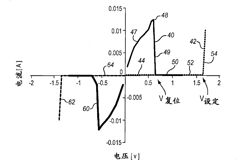
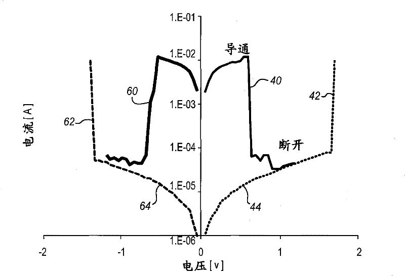
A non-volatile resistive switching memory that includes a material which changes between the insulative and conductive states due to correlations between electrons, particularly via a Mott transition. The material is crystallized into the conductive state and does not require electroforming.

Description

technical field [0001] The present invention relates generally to integrated circuit memories, and more particularly to the formation of non-volatile integrated circuit memories comprising materials exhibiting a change in resistance. Background technique [0002] Non-volatile memory is a class of integrated circuits in which memory cells or elements do not lose their state after power to the device is turned off. The earliest computer memories made with ferrite rings that could be magnetized in two directions were nonvolatile. As semiconductor technology develops to higher miniaturization levels, ferrite devices are abandoned for well-known volatile memories such as DRAM (Dynamic Random Access Memory) and SRAM (Static RAM). [0003] There is always a need for non-volatile memory. Therefore, in the last forty years, many devices have been created to meet this need. In the late 1970s, devices were fabricated with metallization layers connected or not connected to cells. So...

Claims


Application Information

Patent Timeline
Patent Type & Authority Patents(China)
IPC IPC(8): H01L27/10H10B69/00
CPCH01L45/1206H01L45/1675H01L27/2436H01L45/1633H01L45/1608H01L27/101G11C2213/75H01L45/14H01L45/1616H01L45/1625G11C2213/53G11C13/003H01L49/003H01L27/2409G11C2213/79H01L45/146H01L45/145H01L45/10H01L45/144H01L45/1226H01L45/1641H01L45/142H01L45/04H01L45/1233H10B63/20H10B63/30H10N70/20H10N70/823H10N70/023H10N70/021H10N70/041H10N70/026H10N70/8833H10N70/063H10N70/826G11C13/0004
Inventor 卡洛斯·A·帕斯德阿劳若马修·D·布鲁贝克约兰塔·切林斯卡
Owner 思美存储器有限公司
Learn More