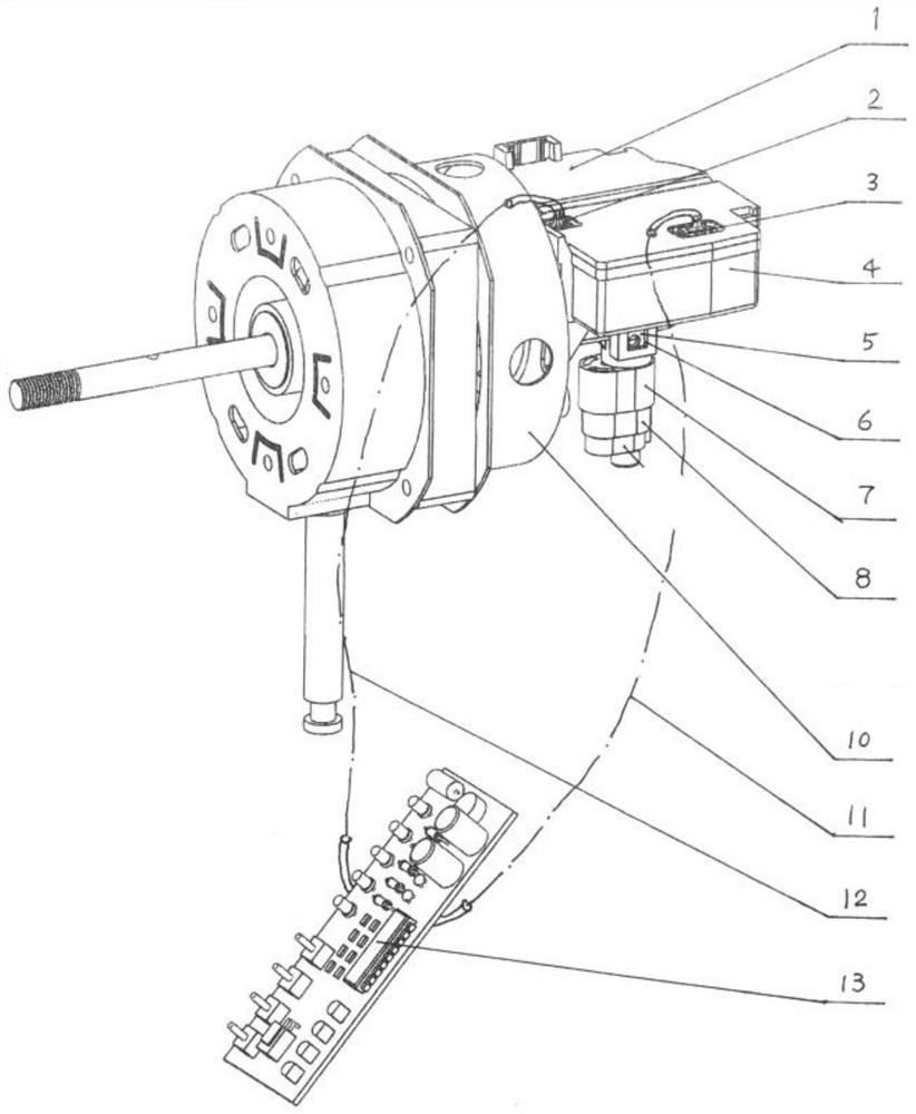
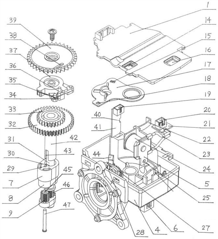
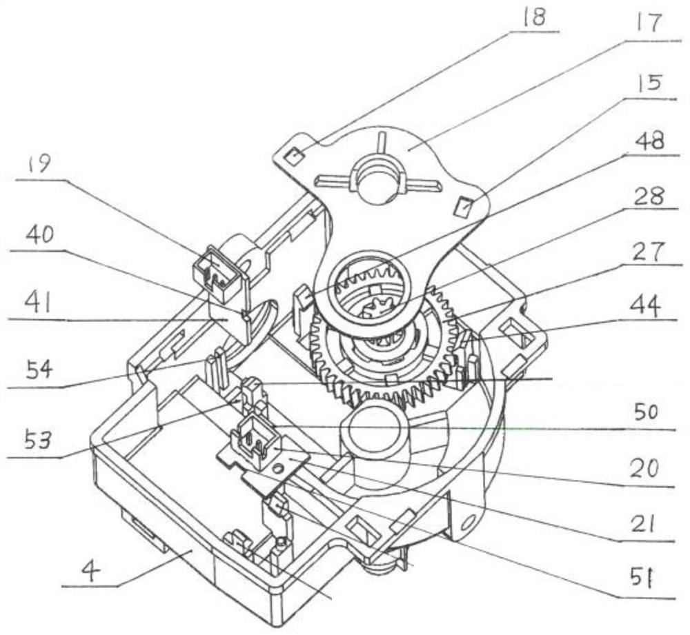
[0003] 1. The crank mechanism of the planetary
gear train in the prior art is a single-ended
cantilever structure, which is affected by the external pulling force of the sun gear on the planetary gear crank and the
cantilever push-
pull force on the remote end of the planetary gear crank by the connecting rod of the electric fan oscillating mechanism. The
joint force will seriously affect the meshing stability of the planetary gear crank and the sun gear. During operation, there will be misalignment,
jumping, wear and
noise between the two. In the locked-rotor test at the factory or when the
impact is blocked by an external force during use, the planetary gear will be damaged. The misalignment of the crank and the sun gear leads to misalignment of the crank of the planetary gear with the reference origin of the original
assembly, resulting in misalignment of the control swing angle
system and failure of angle adjustment
[0004] In order to prevent misalignment in the meshing process between the planetary gear crank and the sun gear, such a planetary gear
train swing angle adjustment enhancement device has been disclosed in the specification of
Chinese Patent No. 02115054.0. The inner edge of the planetary gear and the non-meshing part of the tooth top
circular surface of the sun gear is made with a circular arc reinforcement sleeve. The arc surface is in a dynamic fit state with the tooth top
circular surface corresponding to the planetary gear and the sun gear" (see line 2-line 6 on page 4 of the instruction manual). After adding this arc reinforcement sleeve, the planetary gear crank and the sun The meshing stability of the wheels has been improved, but the newly set "arc reinforcing sleeves are made along the non-meshing parts of the tooth top circular surfaces of the planetary gears and sun gears" is structurally an internally limited tightening structure. During operation, the external pulling force of the sun gear on the planetary gear crank and the combined force of the electric fan oscillating mechanism connecting rod on the
cantilever push-
pull force at the distal end of the planetary gear crank are trapped in the arc surfaces at both ends of the arc reinforcement sleeve. The limited constraints cannot be released, resulting in the teeth of the planetary gear and the sun gear generating a huge
extrusion force and pressure on the top of the tooth on the arc surface of the inner wall of the arc reinforcement sleeve, and because of "the arc at both ends of the arc reinforcement sleeve The center distance is equal to the meshing center distance of the planetary gear and the sun gear", so that there is no gap displacement between the three, which will cause the teeth of the planetary gear and the sun gear to produce overload
extrusion type variable friction, thus affecting the crank mechanism of the planetary
gear system Operating efficiency and service life; and, after the
clutch device is opened during the angle adjustment process, the sun gear under the mandrel is controlled by the
ratchet brake, so that the operation of the three components of the crank mechanism of the planetary
gear system is locked at the mandrel sun gear, and the power of the motor passes through the hollow shaft Input, cause the planetary carrier to revolve, and the output transmission state of the planetary gear crank rotation (revolution and rotation), at this time, because a fixed arc reinforcement sleeve is added at both ends of the tooth circle of the planetary gear and the sun gear, instead of The movable gear ring, one of the three components of the traditional planetary gear
train mechanism, produces a friction braking effect on the tooth tops of the planetary gear and the sun gear, which significantly increases and additionally consumes the power input by the motor through the hollow shaft, and further Cause braking
impact and
extrusion damage between the three components of the crank mechanism of the planetary gear
train; in addition, the scheme also needs to have a positioning shaft that can be fitted with the bearing at the lower part of the planetary gear, and a Bearing fixing plate, the fixing plate has a positioning bearing at the concentric position of the corresponding positioning shaft, and the positioning shaft is concentrically installed in the positioning bearing to form a "dynamic fit" and two screws (see the manual and attached drawings), which has complex structure, many parts, difficult
assembly, Disadvantages of high cost
[0005] Obviously, the above-mentioned shortcoming that the prior art and the planetary gear crank mechanism of the prior art existed need to be perfected
[0006] 2. The large gear in the prior art—the pawl clutch device, since the large gear is an engaging
power transmission component in the
power transmission mechanism, the tooth shape must be an
involute tooth shape. A pawl is pressed against the
involute gear teeth by a bias spring, which also forms a set of large gears—the pawl clutch device. This involute tooth shape has a
structural property that the load is relatively small in the clutch device. Disadvantages: When the load of the electric fan is slightly heavy or slightly blocked, the large gear and the pawl will produce unloading slippage and misalignment, which will cause the planetary gear crank to also be misaligned, resulting in failure of control angle adjustment
[0007] 3. In the worm-worm wheel-worm shaft
pinion-large gear power transmission mechanism in the prior art, a bearing sleeve positioning plate is placed between the worm shaft pinion gear and the large gear, and the bearing sleeve positioning plate is screwed It is fixed on the studs of the plastic gearbox to form a non-slip power transmission mechanism. It is currently the most widely used production process for the entire electric fan oscillating gearbox. However, this screwing process not only requires screws, but also The manufacturer needs to hold the electric screwdriver in one hand, and put the bearing sleeve positioning plate in the other hand, pick up the screws, place the nails, align the nails, and drive the screws into the studs to complete the installation. If you are not careful, the screws will fall into the ground or fall into the gear In the box shell, the nails must be picked up again, and occasionally the screws will be missed in the finished product of the gearbox, which will cause hidden dangers of quality accidents during the final
assembly of the electric fan after leaving the factory. Related structures need to be optimized
[0008] 4. The magnetic braking device in the prior art is fixed on the side wall of the gearbox housing by screwing. This screwing method has the characteristics of reliable installation and convenient maintenance and replacement. However, the magnetic suction The volume space of the braking device installed on the side wall of the gearbox shell is much larger than the conventional volume space of the traditional gearbox, making it difficult to cover and protect the magnetic suction braking device, which does not meet the safety requirements of electric fans; another On the one hand, the production process of screwing the magnetic
brake device to the gearbox shell is a production process that requires nails, labor and takes up space in the gearbox, and needs to be optimized and improved.
[0009] 5. The gearbox product in the prior art is too large in size, the casing has no cover plate, and all parts are bare mounted on the gearbox casing, which violates the safety requirements of the electric fan manufacturing industry. Moreover, the installation format of the naked gearbox , packaging specifications, delivery acceptance standards, and the operation method to the
assembly line of the complete
machine factory are all incompatible with the industry regulations of electric fans, and it is difficult to assemble them with conventional production processes in many complete electric fan factories. This also requires further structural optimization and improvement. of
[0010] 6. At present, most electric fans on the market are AC fans, and their power motors are AC motors, which use AC 220v (or 110v abroad). In the casing, the
AC motor is a high-
voltage component, and the Hall sensor is a DC 5v low-voltage
weak current component, which forms a mixture of high and
low voltage components in the motor casing, resulting in the phenomenon that the Hall sensor has more breakdowns and a low
yield rate, and during assembly and production, There are problems such as complex operation process of high and
low voltage AC and DC motors, incompatibility with the conventional production equipment process of the existing electric fan factory, slow assembly, many secondary breakdowns, difficult disassembly and repair, and high
product defect rate.
[0011] Aiming at the problem of the above-mentioned existing technology that installing Hall sensors in the
AC motor casing forms a mixed installation of high and
low voltage components, resulting in multiple breakdowns and low yields, the applicant demonstrated a method of combining The permanent
magnet magnetic ring is displaced and installed on the rotor shaft of the AC motor rotor protruding out of the casing, and the Hall sensor is correspondingly displaced and installed in the plastic gearbox shell to form a group of non-contact electric fan pendulums isolated from high and low voltage components. Angle adjustment electrical
signal sampling device, so as to avoid problems caused by mixed installation of high and low voltage components
However, due to the
centrifugal force generated on the surface of the rotor shaft caused by the high-speed rotation of the AC motor rotor and the characteristics of
thermal expansion and contraction stress, in this follow-up technical solution, the permanent
magnet magnetic ring is installed on the AC motor rotor protruding out of the casing. The specific method on the rotor shaft and the attached instructions figure 2 The structure shown can neither use mosaic technology nor
adhesive technology, but can only use injection molding technology: first put the
motor shaft and permanent
magnet material into the injection molding The
motor shaft with the permanent magnet magnetic ring installed is pressed into the rotor core, and then the front casing bearing,
washer and
stator of the motor should be installed from the front end of the rotor shaft, and then the rear
washer should be installed from the rear end of the rotor shaft, and the rear casing bearing of the motor should be installed. , at this time, due to the radial obstruction of the permanent magnet magnetic ring fixed on the rear end of the rotor shaft by
hot pressing, parts such as the rear casing bearing of the AC motor cannot pass through the permanent magnet magnetic ring of the rear end of the rotor shaft , so that it cannot be assembled into a complete AC motor. Obviously, the permanent magnet magnetic ring fixed structure and
injection molding process shown in the above follow-up technology have the defects of interference with the conventional AC motor installation process, and need to be improved. Otherwise, The Hall sensor is displaced and installed in the plastic gearbox housing to form a set of high and low voltage components. The corresponding position conditions for isolation cannot be established.


