System for continuously using resist stripper liquid based on nanofiltration

A technology of resist and stripper, which is applied in ultrafiltration, semipermeable membrane separation, photoplate making process of patterned surface, etc., can solve the problems of low heat resistance, difficult filtration speed, and impracticality, and achieve low Low cost and environmental load, and the effect of maintaining stable quality

Inactive Publication Date: 2010-03-31
TOAGOSEI CO LTD
View PDF2 Cites 6 Cited by
  • Summary
  • Abstract
  • Description
  • Claims
  • Application Information

AI Technical Summary

Problems solved by technology

As a nanofiltration membrane having such a fractional molecular weight, as mentioned in Patent Document 1 as a specific example, a membrane mainly composed of an organic substance is common. pressure, it is difficult to increase the filtration speed, it is easy to swell or age through the stripping liquid components, and the heat resistance is low, etc.
Initially, organic nanofiltration membranes are derivatives of ultrafiltration membranes used in artificial dialysis and water purification. Even if they have sufficient strength and stability in water, they are still prone to problems such as aging for organic solvents.
[0008] Paragraph No. [0018] of Patent Document 1 discloses that for the above-mentioned nanofiltration membrane, the resist dissolved in the stripping solution cannot be removed by using a membrane with a fractional molecular weight exceeding 1500.
In addition, paragraph number [0012] of Patent Document 2 discloses: as solvent-resistant filters, ceramic filters such as alumina, zirconia, silicon carbide, silicon nitride, and carbon having an average pore size of about 0.04 to 2 μm, And metal filters such as Mottmetal with an average pore size of about 0.01 to 1 μm; also, solvent-resistant polymer membranes, such as filters made of fluoropolymers, etc., but can trap fractionated molecular weights below 1500 Filters with small pores and sufficient outflow velocity for fine molecules have not yet been put into practical use

Method used


Image

  • System for continuously using resist stripper liquid based on nanofiltration
  • System for continuously using resist stripper liquid based on nanofiltration

Examples


Embodiment 1

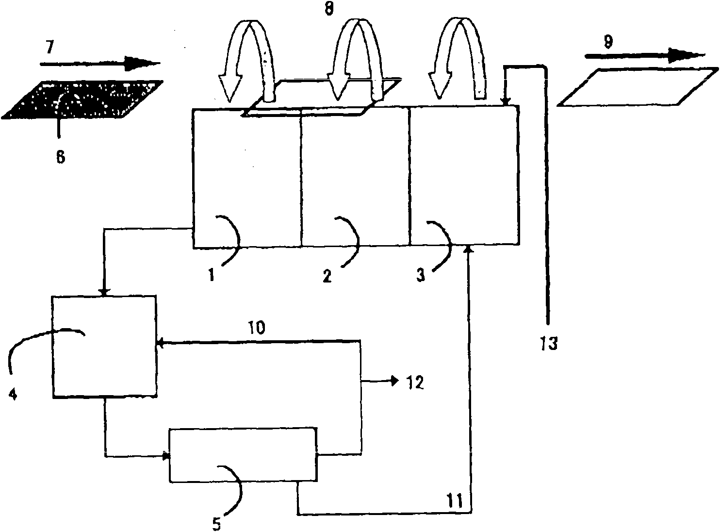
[0043] 100 parts of p-cresol novolak resins are added with 25 parts of positive optical protective agent of naphthoquinone diazide, coated on the glass substrate, and dried to make a 5 μm thick glass substrate with a resist film. figure 1 Place the resist stripping liquid with the composition shown in Table 1 on the resist stripping device, and use as a filter, an alumina aggregate with an average pore diameter of 4 nm and a graded molecular weight of 2000 measured with polyethylene glycol. Titanium, area 1.2m 2 tubular ceramic filter. On the filter surface, the flow velocity of the concentrated stripping liquid in the direction parallel to the filter surface is 2m / s, and the flow velocity of the processed stripping liquid side after filtration is not controlled and allowed to flow out freely. In addition, on the side of the stripping liquid containing the resist component of the filter, the inflow pressure of the pump entering the filtration process was set so that a pressur...

Embodiment 2

[0054] Resist stripping was performed in the same operation method as in Example 1, except that a ceramic filter having the same material, an average pore diameter of 2 nm, and a fractional molecular weight of 1,000 was used as a filter.

[0055] [table 3]

[0056] Concentration of resist components in the stripping bath of Example 2

[0057] Running time (minutes)

0

100

1000

2000

3000

Blocking rate (%)

92

92

92

92

Strip tank 1 concentration

0

0.07

0.36

0.46

0.53

Stripping Tank 2 Concentration

0

0.001

0.04

0.1

0.16

Strip tank 3 concentration

0

0.0

0.02

0.07

0.12

Filtrate outflow velocity (L / h m 2 )

6

6

3

3

3

[0058] (The unit of resist component concentration is mass %)

[0059] After 100 minutes, the resist component concentration of the stripping solution containing resist compo...

Embodiment 3

[0061] The resist stripping was carried out in the same operation method as in Example 1, except that a ceramic filter having an average pore diameter of 5 nm and a fractional molecular weight of 4,000 having the same material as the filter was used.

[0062] [Table 4]

[0063] Concentration of resist components in the stripping bath of Example 3

[0064] Running time (minutes)

0

100

1000

2000

3000

Blocking rate (%)

71

72

72

72

Strip tank 1 concentration

0

1.9

1.8

1.8

1.8

Stripping Tank 2 Concentration

0

1.6

1.5

1.5

1.5

Strip tank 3 concentration

0

1.4

1.3

1.3

1.3

Filtrate outflow velocity (L / h m 2 )

22

20

18

18

18

[0065] (The unit of resist component concentration is mass %)

[0066] After 100 minutes, the resist component concentration of the stripping solution containing the r...


PUM

PropertyMeasurementUnit
pore sizeaaaaaaaaaa
pore sizeaaaaaaaaaa
pore sizeaaaaaaaaaa

Abstract

The object of the invention is to realize a system in which a resist stripper liquid used in resist stripping is regulated so as to have a resist component concentration within a certain concentrationrange even when the resist stripper liquid is continuously used for long without replacing it. In stripping a positive resist with a stripper liquid, the resist components which have dissolved in thestripper liquid can be diminished by cross-flow filtration with a specific ceramic filter (5). In the resist stripping system, a resist-component-containing stripper liquid resulting from a strippingstep is treated in a filtration step, and the resultant concentrated stripper liquid having a heightened resist-component concentration is suitably discharged from the system. A fresh stripper liquidis suitably added to the stripper liquid from which the resist components have been removed, and the resultant stripper liquid is reused in the stripping step.

Description

technical field [0001] The present invention relates to a resist stripping process performed in the manufacturing process of electronic components such as semiconductors, liquid crystals, and printed wiring boards, and to a system for performing resist stripping while processing a resist stripping solution containing a resist component. Background technique [0002] In the manufacturing process of electronic components such as semiconductors, liquid crystals, and printed wiring substrates, including: Si wafers or substrates on which semiconductor thin films are laminated on the glass surface, etc., a photoresist or a photosensitive film of resist is formed. mold, after the irradiation process of irradiating light, etc.; after the development process of dissolving unnecessary photoresist with a developer, the stripping process of stripping the remaining resist; in the above stripping process, generally used for stripping Resist stripping solution for resist. [0003] In rece...

Claims


Application Information

Patent Timeline
Patent Type & Authority Applications(China)
IPC IPC(8): H01L21/027B01D61/14B01D71/02G03F7/42H01L21/304
CPCB01D61/027G03F7/422G03F7/3092G03F7/425
Inventor 住田正直林秀生
Owner TOAGOSEI CO LTD
Why Eureka
Try Eureka