
Method for detecting neural signal of spinal cord for long term and positioning exciting electrode

A spinal nerve and excitation electrode technology, used in diagnostic recording/measurement, medical science, sensors, etc., can solve the problems of large surgical trauma, poor signal-to-noise ratio, insufficient excitation, etc. Small effect of spinal cord injury

Inactive Publication Date: 2010-05-12
SOUTHEAST UNIV
View PDF0 Cites 4 Cited by
  • Summary
  • Abstract
  • Description
  • Claims
  • Application Information

AI Technical Summary

Problems solved by technology

The disadvantages are: 1) the detected signal components are complex, which is the sum of all neuron signals in the nerve tissue, and the signal-to-noise ratio is poor; 2) the channel selectivity of the electrodes is poor, and when it is necessary to excite neurons or nerve fibers at specific locations, it is inevitable The ground will stimulate all neurons or nerve fibers at the same time; 3) The functional electrical excitation voltage usually needs more than 5V, which is not compatible with the low voltage and low power consumption required by biological integrated circuits, and the integrated circuits using 3.3V voltage will produce insufficient excitation. question
But there are the following disadvantages: 1) The main body of the electrode material is semiconductor silicon, not a good conductor metal, the contact impedance between the electrode and the nerve bundle is high, and the voltage amplitude required to excite the action potential is higher than that of the metal acupuncture needle electrode; 2) Array The position and the height of the needle are fixed, and it is impossible to achieve "needling according to the symptoms"; 3) Laminectomy is also required to place the electrode during implantation, and the surgical trauma is still too large

Method used


Image

  • Method for detecting neural signal of spinal cord for long term and positioning exciting electrode
  • Method for detecting neural signal of spinal cord for long term and positioning exciting electrode

Examples


Embodiment Construction

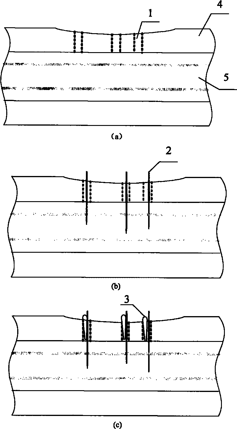
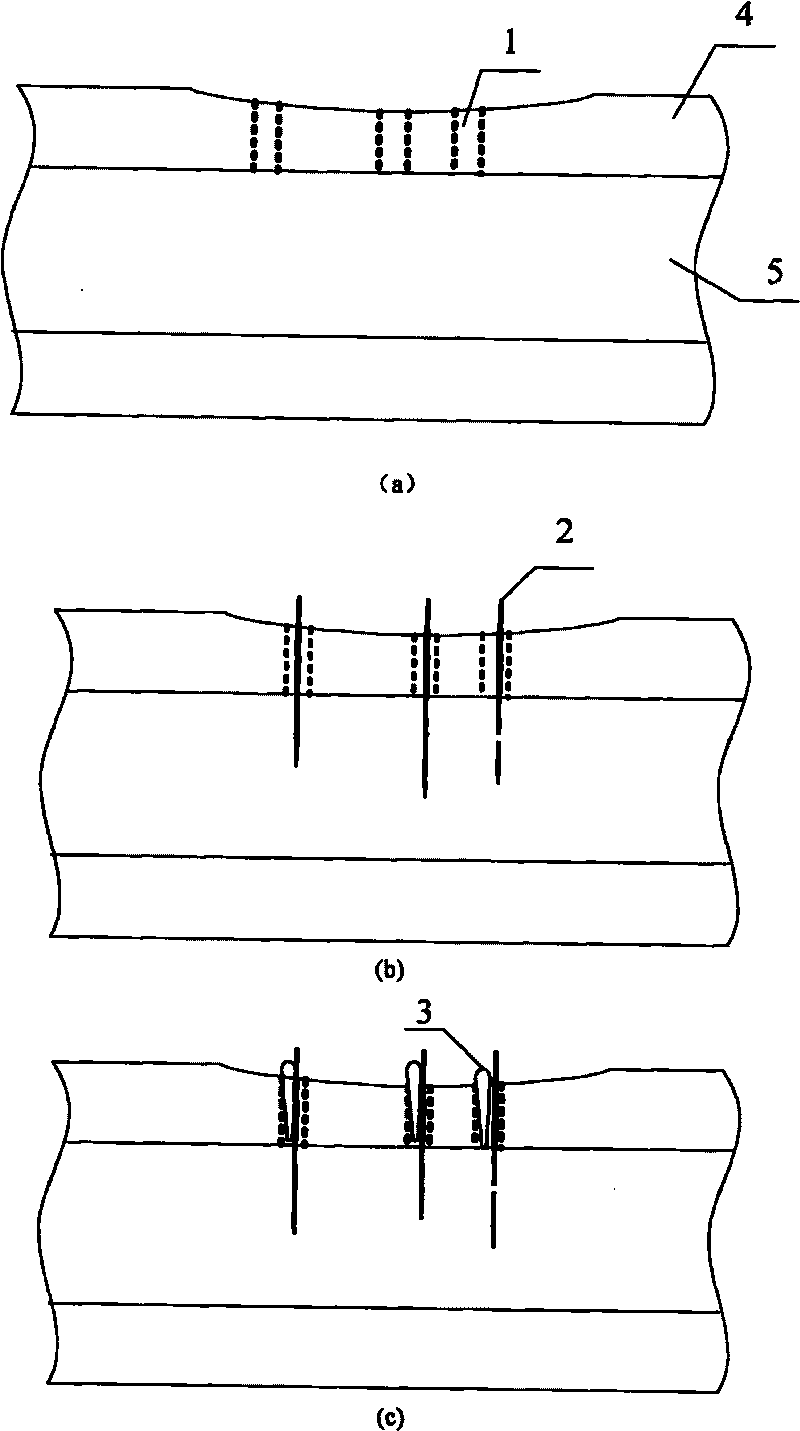
[0024] A positioning method for long-term detection and excitation electrodes of spinal nerve signals:

[0025] Step a: use a special bone drill to drill holes 1 distributed according to requirements on the vertebra 4,

[0026] Step b: use the microelectrode pusher to insert the acupuncture electrode 2 through the opening 1 to the spinal nerve 5 to be detected or stimulated,

[0027] Step c: Insert a conical gutta-percha tip .3. into the hole .1. where the acupuncture electrode .2. is inserted, so that the acupuncture electrode .2. is fixed. In this embodiment, the diameter of the drill bit of the bone drill is 2 to 3 times the diameter of the acupuncture electrode.

[0028] Below in conjunction with accompanying drawing, the present invention is described in detail, and implementation method is: at first drill hole 1 on experimental animal vertebrae 4 with special bone drill to form the distribution of holes 1 that needs, and the diameter of drill bit is about 2~3 times of a...


PUM


Abstract

The invention discloses a method for detecting the neural signal of spinal cord for long term and positioning an exciting electrode. The method comprises the following steps: 1. drilling holes which are distributed according to a demand with a special bone drill on the vertebra; 2. inserting the acupuncture electrodes in the spinal nerves to be detected or excited with a microelectrode propeller through the holes; and 3. inserting conical gutta-percha points in the holes which are firstly inserted the acupuncture electrodes to fix the acupuncture electrodes. Compared with the prior art, the method of the invention has small wound, simple operation and flexible use, the three-dimension electrode distribution which can meet any demand is realized, and the electrodes are shortened to be in level with the surface of the bone so that the electrodes can be buried under the skin, thus the electrodes can not damage the skin and be hit, and the electrodes can not be damaged, thus having safety and reliability.

Description

technical field [0001] The invention relates to a positioning method for detection or excitation electrodes of vertebrate spinal cord nerve signals. In particular, a simple and flexible electrode positioning and fixing method for long-term detection and excitation of spinal nerve signals. Background technique [0002] Nerve electrodes, as detectors and exciters of nerve signals, and as interfaces between biological information systems and electronic information systems, have important scientific significance and extensive application value in life science research and neural function reconstruction, and are very important components. [0003] Currently commercially available array electrodes include cuff electrodes and Utah electrodes. The cuff electrode is a planar nerve external electrode. The electrode points are made on the surface of flexible and non-toxic polyimide, and a slit roll is naturally formed after it is made. The surface of the electrode array located on th...

Claims


Application Information

Patent Timeline
Patent Type & Authority Applications(China)
IPC IPC(8): A61B5/04
Inventor 王志功吕晓迎沈晓燕黄宗浩
Owner SOUTHEAST UNIV
Learn More