
Multifunctional high-efficiency aerator and using method thereof

An aerator and multi-functional technology, applied in chemical instruments and methods, water aeration, sustainable biological treatment, etc., can solve problems such as aeration dead zone, achieve the elimination of air bubbles, lower cost, and high mass transfer rate Effect

Inactive Publication Date: 2010-07-07
宜兴阳源环境工程有限公司
View PDF0 Cites 19 Cited by
  • Summary
  • Abstract
  • Description
  • Claims
  • Application Information

AI Technical Summary

Problems solved by technology

Jet aeration, using the negative pressure generated by the high-speed water flow through the throat, sucks in the air, mixes it and sprays it out, this form is easy to form an aeration dead zone

Method used


Image

  • Multifunctional high-efficiency aerator and using method thereof
  • Multifunctional high-efficiency aerator and using method thereof
  • Multifunctional high-efficiency aerator and using method thereof

Examples


Embodiment 1

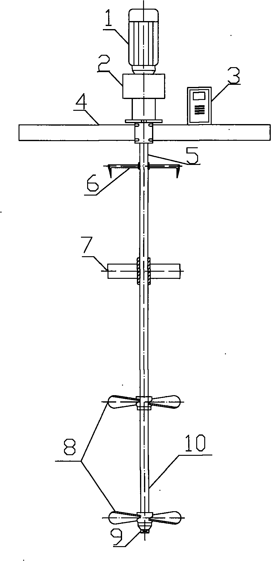
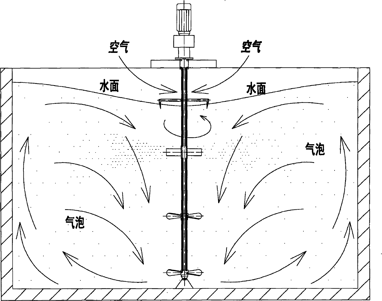
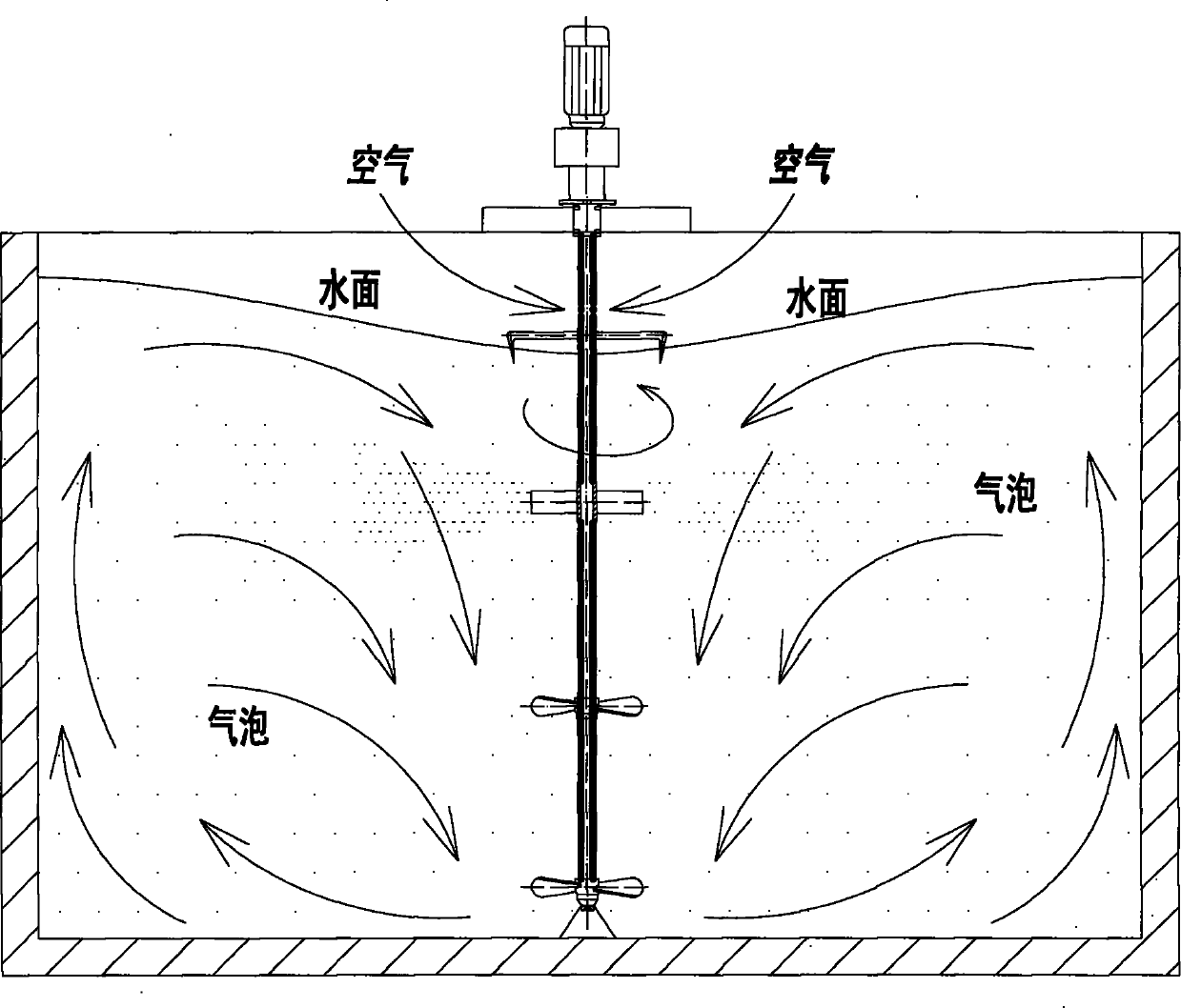
[0017] Embodiment 1: when needing aeration, start motor 1, drive hollow shaft 10 and the impeller on the shaft to rotate, when air-breathing turbine 7 reaches critical speed (200-450r / min), produces enough big near air-breathing turbine 7 Negative pressure, a large amount of air is sucked in through the air hole 5 on the hollow shaft 10, and is ejected from the air outlet hole between the suction turbine 7 through the hollow shaft 10, under the action of the shear force and dynamic pressure change force near the suction turbine 7 , produce very small micro-bubbles, greatly increasing the specific surface area of ​​the bubbles. The defoaming paddle 6 can chop the foam on the water surface, and the upflow and downflow circulating in the pool make the liquid surface constantly updated, bringing the foam on the liquid surface to the bottom of the pool, and the foam is driven to change the local thickness of the bubble surface, while the water flow The pressure on the surface of th...

Embodiment 2

[0018] Example 2: When it is necessary to remove nitrogen and phosphorus from sewage, the sewage treatment process needs to be switched between aerobic, anoxic and anaerobic modes. Start the motor 1 to drive the hollow shaft 10 and the impeller on the shaft to rotate. When the suction turbine 7 reaches the critical speed (200-450r / min), a large enough negative pressure will be generated near the suction turbine 7, and the air will flow from the hollow shaft 10 A large amount of air holes 5 in the air are inhaled, and are ejected from the air outlet holes between the air-intake turbines 7 through the hollow shaft 10. Under the action of the shear force and dynamic pressure change force near the air-intake turbine 7, very small micro-bubbles are generated, which greatly increases the The specific surface area of ​​the bubbles. The defoaming paddle 6 can chop the foam on the water surface, and the upflow and downflow circulating in the pool make the liquid surface constantly upda...


PUM


Abstract

The present invention provides a multifunctional high-efficiency aerator and using method thereof, comprising the following steps: when aeration, starting an electric motor to drive a hollow shaft, a de-foaming paddle, an air inhaling turbine and stirring impellers to rotate; inhaling air by an air hole at the upper end of the hollow shaft and spraying out from a pore in the turbine when rotation speed of the air inhaling turbine reaches to the critical rotation speed; simultaneously, dispersing big bubbles to fine micro-bubble by shearing force nearby the turbine and fluctuant force of dynamic pressure; cutting and crushing big bubbles by the de-foaming paddle; simultaneously, forming axial flow under the actions of the stirring impellers and continuously updating liquid level; bringing foam on surface to the bottom of the pool; uniformly dispersing bubbles in a reactor under the mixing and stirring of the stirring impellers; forming a suspending state for mud; achieving complete contact of three-phase of air-solid-liquid. The aeration method provided in the present invention has high mass transfer rate of oxygen, good oxygenation effect and strong property for suiting environment.

Description

technical field [0001] The invention relates to sewage treatment equipment and a method thereof, in particular to a multifunctional high-efficiency aerator and a method for using the same. Background technique [0002] At present, the known aeration methods mainly include blast aeration and mechanical aeration. The blower aeration system consists of a blower, an aerator and a series of connected pipelines. A blower sends air through a series of pipes to an aerator installed at the bottom of the pool, where it passes the air into bubbles of various sizes. Bubbles are formed at the outlet of the aerator, and the size depends on the form of the air diffusion device. The bubbles rise and flow with the water ring, and finally break at the liquid surface. This process produces the transfer of oxygen to the sewage. The aerators of the blower system are mainly divided into micro-bubbles, medium-bubbles, and large-bubbles. [0003] There are many forms of microporous aerators. At ...

Claims


Application Information

Patent Timeline
IPC IPC(8): C02F7/00C02F3/30
CPCY02W10/10
Inventor 蒋阳亮章北平冯振鹏黄晓辉金儒霖
Owner 宜兴阳源环境工程有限公司
Learn More