Clock data restorer

A technology of clock data recovery and output clock, applied in the direction of electrical components, automatic power control, etc., to achieve the effect of stable performance

Inactive Publication Date: 2010-07-14
FARADAY TECH CORP
View PDF1 Cites 14 Cited by
  • Summary
  • Abstract
  • Description
  • Claims
  • Application Information

AI Technical Summary

Problems solved by technology

[0015] The purpose of the present invention is to provide a clock data restorer to solve the problem that the circuit design of the clock dat

Method used


Image

  • Clock data restorer
  • Clock data restorer
  • Clock data restorer

Examples


Embodiment Construction

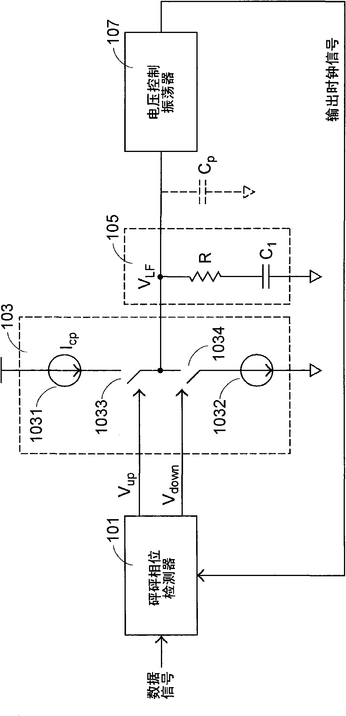
[0039] In order to improve the limitations caused by the inconsistency of the resistance and capacitance characteristics of the loop filter in the current technology when implementing the clock data restorer, some designs currently propose Figure 3a method, which is a schematic diagram of using a proportional path to realize the design of a clock data restorer. The difference between this method and the prior art method is mainly: to change the design of connecting the resistor and the capacitor in series in the loop filter 305 in the prior art, only Reserve the integration capacitor C coupled between the output terminal of the charge charge pump 103 and the voltage control oscillator 307, and additionally connect the judgment signal (V up , V down ) is connected to the voltage controlled oscillator 307.

[0040] Through such a design method, the circuit of the clock data restorer can be divided into two paths, which are the proportional path connected to the voltage-control...


PUM


Abstract

The invention discloses a clock data restorer, which comprises a phase detector, an electric charge charging pump, a loop filter, a voltage control oscillator, a current adjusting module, a current control oscillator and a frequency eliminator, wherein the phase detector compares a data signal with a first output clock signal and then generates a judgment signal; the electric charge charging pump converts the judgment signal into a switching signal; the loop filter converts the switching signal into a control voltage; the voltage control oscillator adjusts a generated second output clock signal according to the control voltage, and comprises a current mirror which is provided with a current control path and a current output path between which currents are in a proportional relation, and a control circuit which changes the current of the current control path according to the control voltage; the current adjusting module outputs difference current according to the judgment signal; the current control oscillator adjusts the phase of the second output clock signal according to the sum of the difference current and the current of the current output path; and the frequency eliminator converts the second output clock signal into the first output clock signal. The clock data restorer of the invention does not become a three-order system due to the influence of a parasitic capacitor or a decoupling capacitor.

Description

technical field [0001] The present invention relates to a clock data restorer, in particular to a clock data restorer with a proportional path. Background technique [0002] The role of the phase detector (phase detector, PD) is to receive and compare the data signal and the output clock signal to generate a judgment signal, and the phase detector is often used in the phase locked loop (Phase Locked Loop, PLL) to act as a clock or frequency Precise control, in addition, the method of phase-locked loop is also used in the clock data recovery (Clock Data Recovery, CDR) circuit. [0003] Please refer to FIG. 1 , which is a schematic diagram of the adjustment relationship of phase detectors divided into two types: linear phase detectors and bang-bang phase detectors according to the phase adjustment methods. in Figure 1a It is a correction method of a linear phase detector. When the phase difference value ψ is larger, the value of the phase correction Δψ will increase proporti...

Claims


Application Information

Patent Timeline
IPC IPC(8): H03L7/085H03L7/099
Inventor 魏呈达余明士
Owner FARADAY TECH CORP
Why Eureka
Try Eureka