Defoaming method adopting porous ceramics
A porous ceramic and defoaming technology, applied in the direction of foam dispersion/prevention, etc., can solve the problems of defoaming agent increasing production cost, affecting product performance, and there is no universally applicable defoaming technology, achieving low cost, safe operation, The effect of universal applicability
- Summary
- Abstract
- Description
- Claims
- Application Information
AI Technical Summary
Problems solved by technology
Method used
Image

Examples
Embodiment 1
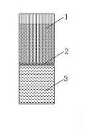
[0022] The solution is heated or reacts violently, and a large amount of foam is generated above the solution. For example, a large amount of foam is generated during the solution evaporation process in a tube heat exchanger. A porous ceramic with a hydrophobic treatment and a pore size smaller than the foam diameter is used. The porous ceramic 1 is placed on the In the foam flow line above solution 3, such as figure 1 As shown, in the process of continuous generation and rising of the foam 2, the foam is torn and broken by passing through the porous ceramic.
[0023] According to the characteristics of the foam produced and the size of the foam, the porous ceramics used can choose the relationship between different pores or the porous ceramics with different pore diameters. Porous ceramics, the applicable porous ceramics in this example are ① high siliceous silicate material porous ceramics: use hard porcelain slag, acid-resistant ceramic slag and other acid-resistant synthet...
Embodiment 2
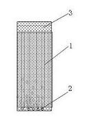
[0026] The solution is heated or the reaction is relatively moderate, and the foam 2 is generated inside the solution 3, such as in the process of ore dressing, water and wastewater treatment, etc., or the bubbles that are too stable and need to be eliminated are added. Such bubbles will not overflow the liquid surface in large quantities, but Existing in the solution will affect the stability of the solution and reduce the treatment effect. Porous ceramics with a hydrophobic treatment and a pore size smaller than that of the foam are used to install the porous ceramics 1 inside the solution 3, such as figure 2 As shown, the solution is passed through the pipe filled with porous ceramics, and the bubbles in the solution are torn and broken when passing through the pores of the porous ceramics, and finally defoaming is achieved.
[0027] According to the characteristics of the foam produced and the size of the foam, the porous ceramics used can choose the relationship between ...
Embodiment 3
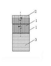
[0030] The solution is heated or the reaction is extremely violent, and a large number of foams are generated and gathered above the solution. For example, a large number of foams generated in the evaporation process of a certain viscous solution (such as waste water evaporation, high-temperature and high-pressure dehydration of crude oil, etc.) are treated with hydrophobic treatment, and the pore size is smaller than the foam. diameter of porous ceramics, the porous ceramic 1 is placed in the foam flow pipeline above the solution 3 in multiple layers, for the working condition that the foam 2 cannot be completely eliminated in the pores of the porous ceramic body, according to the amount of foam generated and eliminated during production, the porous ceramic The body adopts different rates of forward or reverse rotation, such as image 3 As shown, the ceramic body and spacing can be adjusted according to the size of the foam. When the foam in the porous ceramic channel that is ...
PUM
 Abstract
Description
Claims
Application Information
 - R&D
- Intellectual Property
- Life Sciences
- Materials
- Tech Scout
- Unparalleled Data Quality
- Higher Quality Content
- 60% Fewer Hallucinations
Browse by: Latest US Patents, China's latest patents, Technical Efficacy Thesaurus, Application Domain, Technology Topic, Popular Technical Reports.
© 2025 PatSnap. All rights reserved.Legal|Privacy policy|Modern Slavery Act Transparency Statement|Sitemap|About US| Contact US: help@patsnap.com