
Method for recovery of contaminated groundwater through in situ enhanced aeration

An in-situ strengthening and groundwater technology, applied in chemical instruments and methods, water aeration, water/sludge/sewage treatment, etc., can solve problems such as high tailing concentration, slow removal of pollutants, and limited removal efficiency of pollutants , to achieve the effects of small environmental impact, low cost, and accelerated removal rate

Inactive Publication Date: 2011-07-20
JILIN UNIV
View PDF0 Cites 2 Cited by
  • Summary
  • Abstract
  • Description
  • Claims
  • Application Information

AI Technical Summary

Problems solved by technology

[0004] However, through laboratory and field research, it is found that the existing AS technology still has some disadvantages: the air flow is only limited in a few narrow channels near the aeration well, and most pollutants can only be removed by diffusion into the channels first. , Therefore, the diffusion effect greatly limits the removal efficiency of pollutants [Document 1: Ji W, Dahmani A, Ahlfeld D P, et al.1993.Laboratory study of air sparging: air flowvisualization.Ground Water Monit R, 13(4): 115-126], resulting in slow pollutant removal and high tailing concentration

Method used


Image

  • Method for recovery of contaminated groundwater through in situ enhanced aeration
  • Method for recovery of contaminated groundwater through in situ enhanced aeration

Examples


Embodiment 1

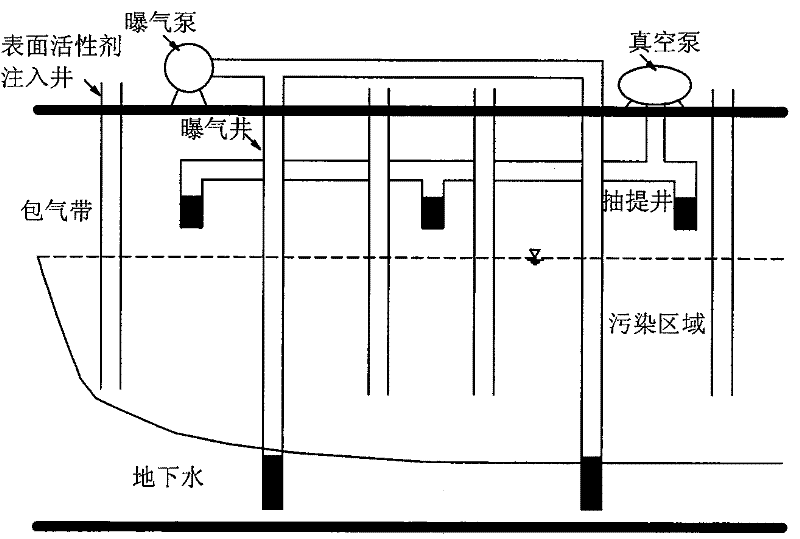
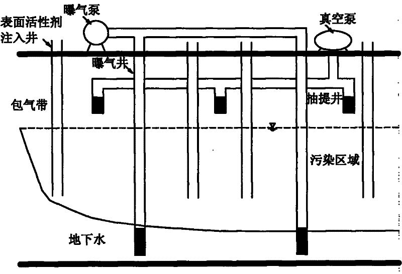
[0025] a. Drill 4 surfactant injection wells in the groundwater polluted area. The distance between the injection wells is 5m. For the polluted groundwater layer, three extraction wells should be drilled, the distance between the extraction wells is 5m, the extraction wells do not penetrate the vadose zone, and the bottom of the well is close to the groundwater surface in the vadose zone; the aeration wells and extraction wells are arranged in Surfactant injection between wells;

[0026] b. Connect the surfactant storage tank to the surfactant injection well through the pipeline, connect the aeration pump to the aeration well through the pipeline, and connect the extraction well to the extraction pump through the pipeline;

[0027] C, anionic surfactant sodium dodecylbenzene sulfonate is injected into the amount of 400mg / liter per liter of groundwater, injected into the groundwater polluted area by injection pump, sodium dodecylbenzenesulfonate is dissolved in groundwater, in ...

Embodiment 2

[0031] a. Drill 3 surfactant injection wells in the groundwater polluted area. The distance between the injection wells is 3m. For the polluted groundwater layer, two extraction wells should be drilled, the distance between the extraction wells is 2m, the extraction wells do not penetrate the vadose zone, and the bottom of the well is close to the groundwater surface in the vadose zone; the aeration well and the extraction well are arranged in Surfactant injection between wells;

[0032] b. Connect the surfactant storage tank to the surfactant injection well through the pipeline, connect the aeration pump to the aeration well through the pipeline, and connect the extraction well to the extraction pump through the pipeline;

[0033] c. Inject the anionic surfactant sodium lauryl sulfate at 200mg / liter per liter of groundwater into the groundwater polluted area through an injection pump, so that sodium lauryl sulfate dissolves in the groundwater and forms a surface in the ground...

Embodiment 3

[0037] a. Drill 6 surfactant injection wells in the groundwater polluted area. The distance between the injection wells is 7m. For the polluted groundwater layer, 5 extraction wells should be drilled, the distance between the extraction wells is 7m, the extraction wells do not penetrate the vadose zone, and the bottom of the well is close to the groundwater surface in the vadose zone; the aeration wells and extraction wells are arranged in Surfactant injection between wells;

[0038] b. Connect the surfactant storage tank to the surfactant injection well through the pipeline, connect the aeration pump to the aeration well through the pipeline, and connect the extraction well to the extraction pump through the pipeline;

[0039] c, the non-ionic surfactant Tween 80 is injected into the groundwater polluted area by the injection pump at the amount of 100mg / liter per liter of groundwater, so that the surfactant Tween 80 is dissolved in the groundwater, and the surface tension for...


PUM

PropertyMeasurementUnit
surface tensionaaaaaaaaaa

Abstract

The present invention relates to a method for recovery of contaminated groundwater through in situ enhanced aeration, which comprises the following steps: digging more than one surfactant injection well, an aeration well and an extraction well in an area with the groundwater contaminated, injecting surfactant into the area with the groundwater contaminated through the surfactant injection well to dissolve the surfactant into the groundwater so as to form surface tension in the area with the groundwater contaminated, starting the extraction pump to pump an aeration zone into negative pressure, and starting the aeration pump for continuous aeration. The method for recovery of contaminated groundwater through in situ enhanced aeration provided by the present invention effectively solves the problem that the majority of pollutants can be removed only after flowing into the porous channel through diffusion due to the narrow porous channel near the aeration well, and improves the saturation degree of the air in the groundwater, thereby increasing opportunities of exposure the pollutants to the air. Tests show that, when the aeration rate is 100ml / min, the surface tension is reduced to 50.4dyn / cm from 70.5dyn / cm, the half-life for removal of the pollutant chlorobenzene is reduced to 16min from 31min, and simultaneously the trailing concentration is reduce to 5.1mg / L from 22.08mg / L. The removal rate can be increased to 98.5 percent from 89.2 percent after 420 minutes. The method for recovery of contaminated groundwater through in situ enhanced aeration provided by the present invention has the advantages of simple process, low cost, low surfactant injection and less impact on the environment.

Description

Technical field: [0001] The invention relates to the treatment of groundwater polluted by organic pollutants, in particular to a method for strengthening groundwater aeration and repairing groundwater through surfactants. Background technique: [0002] In recent years, with the rapid development of my country's economy and society, environmental pollution incidents have occurred frequently, especially the high-concentration, highly toxic organic pollutants and high-intensity site pollution caused by major environmental pollution incidents such as explosions, leaks, and illegal discharges. pose a serious threat. [0003] Groundwater aeration technology (air sparging, AS) is considered to be the most effective method for removing VOCs from saturated soil and groundwater. By injecting fresh air into the aquifer, due to the effect of buoyancy, air-borne pollutants gradually rise and are collected by gas-phase extraction wells in the vadose zone, thereby achieving the purpose of ...

Claims


Application Information

Patent Timeline
Patent Type & Authority Patents(China)
IPC IPC(8): C02F7/00
CPCY02W10/10
Inventor 赵勇胜秦传玉郑苇张兰英邹东雷
Owner JILIN UNIV
Learn More