Back-light black-surface silicon solar battery structure and production method thereof

A solar cell and backlight technology, applied in photovoltaic power generation, circuits, electrical components, etc., can solve the problem of inability to absorb, and achieve the effects of increasing photocurrent, avoiding open circuit voltage, and improving photoelectric conversion efficiency.

Inactive Publication Date: 2010-08-18
INST OF SEMICONDUCTORS - CHINESE ACAD OF SCI
View PDF0 Cites 21 Cited by
  • Summary
  • Abstract
  • Description
  • Claims
  • Application Information

AI Technical Summary

Problems solved by technology

[0007] In view of this, the main purpose of the present invention is to propose a backlight black silicon solar cell structure and its manufacturing method, to solve the problem that traditional silicon-based cells cannot absorb and convert the solar spectrum with a wavelength of 1.1 μm or more due to the limitation of infrared absorption, and improve the solar energy efficiency of silicon. Photoelectric conversion efficiency of solar cells

Method used


Image

  • Back-light black-surface silicon solar battery structure and production method thereof
  • Back-light black-surface silicon solar battery structure and production method thereof
  • Back-light black-surface silicon solar battery structure and production method thereof

Examples


Embodiment 1

[0046] Embodiment 1: The backlight black silicon solar cell structure on the n-type silicon-based substrate see figure 2 , the implementation process is as follows: on the front side of the n-type silicon-based substrate, a boron-doped gradient layer is formed by boron diffusion or deposition of gradient boron-doped polysilicon or gradient boron-doped amorphous silicon, and the boron-doped gradient layer is woven by chemical etching. structure or laser irradiation to form a light-trapping layer on the light-receiving side; on the back of the n-type silicon-based substrate, make black silicon doped with chalcogenide impurities by laser irradiation to form a back-light-doped n-type black silicon layer; The silicon oxide dielectric passivation is performed on the light-facing and back-light sides of the battery, and the front contact gate electrode, the back contact electrode, and the metal layer of the back-counter electrode are made respectively, that is, the back-light black si...

Embodiment 2

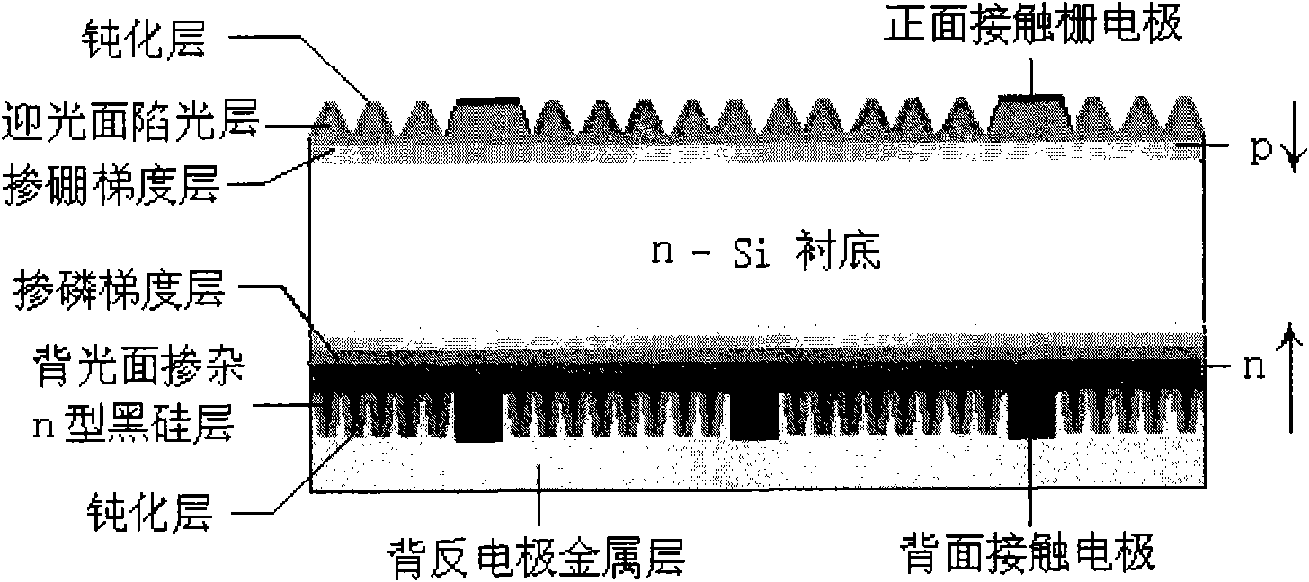
[0047] Example 2: The structure of black silicon solar cells on the backlight surface with gradient phosphorus doping introduced on the n-type silicon-based substrate is shown in image 3 , the implementation process is as follows: on the back of the n-type silicon-based substrate, a phosphorous-doped gradient layer is formed from the surface to the inner surface and the phosphorus concentration is gradually reduced by diffusing or depositing a gradient phosphorus-doped polysilicon or gradient phosphorus-doped amorphous silicon layer. The surface of the phosphorus-doped gradient layer is irradiated with black silicon doped with chalcogenide impurities by laser light to form an n-type black silicon layer doped on the backlight surface; on the front side of the n-type silicon-based substrate, boron-doped polycrystalline silicon or Gradient boron-doped amorphous silicon forms a boron-doped gradient layer with decreasing boron concentration from the surface to the inside, and a lig...

Embodiment 3

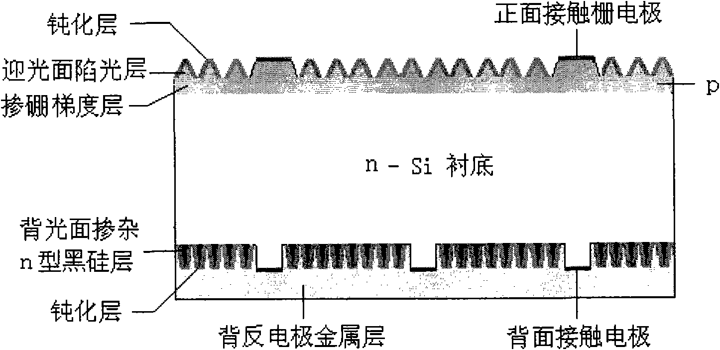
[0048] Example 3: The backlight black silicon solar cell structure on the p-type silicon-based substrate see Figure 4 , the implementation process is as follows: on the front side of the p-type silicon-based substrate, a light-trapping layer on the light-facing surface is formed by chemical etching or laser irradiation; black silicon to form a doped n-type black silicon layer on the backlight surface; then perform silicon oxide dielectric passivation on the light-facing and back-light sides of the battery according to the conventional process, and make the front contact gate electrode, the back contact electrode and the back-counter electrode metal layer respectively. That is, the fabrication of the backlight black silicon solar cell structure on the p-type silicon-based substrate is completed.


PUM

PropertyMeasurementUnit
thicknessaaaaaaaaaa
depthaaaaaaaaaa
thicknessaaaaaaaaaa

Abstract

The invention discloses a back-light black-surface silicon solar battery structure, which comprises a silicon-based substrate, a light trapping material layer which is formed at the front side of the silicon-based substrate and a broad-spectrum absorbing black silicon material layer which is formed at the back side of the silicon-based substrate. The invention further discloses a method for producing the back-light black-surface silicon solar battery structure. The invention can adequately use the characteristic of the broad-spectrum absorption of the black silicon material, thereby leading the sunlight which enters into the battery nearly to be completely absorbed, making a contribution to light current, solving the problem that the conventional silicon-based battery can not absorb and transfer solar spectrum with the wavelength which is more than 1.1mu m under the limitation of the infrared absorption, and effectively improving the photoelectric conversion efficiency of the silicon-based solar battery.

Description

technical field [0001] The invention relates to the technical field of silicon-based solar cells, in particular to a backlight black silicon solar cell structure and a manufacturing method thereof. Background technique [0002] Solar energy is an inexhaustible, non-polluting, renewable and clean energy with the greatest potential for development. The silicon material abundant on the earth is the best material for making solar cells. However, the cost of power generation of silicon-based cells is still relatively high at present. It is difficult to popularize civilian use. An important way to reduce the price of electricity generated by silicon-based solar cells is to improve the photoelectric conversion efficiency of the cells. The main technical means currently used are to reduce the reflectivity of light on the surface of the battery, such as the use of transparent anti-reflection electrode film, pyramid textured surface, porous silicon light-trapping surface structure, e...

Claims


Application Information

Patent Timeline
Patent Type & Authority Applications(China)
IPC IPC(8): H01L31/068H01L31/0236H01L31/18H01L31/20
CPCY02E10/50Y02E10/546Y02E10/547Y02P70/50
Inventor 朱洪亮朱小宁刘德伟马丽赵玲娟
Owner INST OF SEMICONDUCTORS - CHINESE ACAD OF SCI
Why Eureka
Try Eureka