Method and device for measuring optical axis and gap of lens group by differential confocal internal focusing method

A differential confocal, measurement method technology, applied in the direction of measurement device, optical device, optical performance test, etc., to achieve the effect of reducing measurement error, increasing working distance, and fast measurement speed

Inactive Publication Date: 2010-08-25
BEIJING INSTITUTE OF TECHNOLOGYGY
View PDF8 Cites 21 Cited by
  • Summary
  • Abstract
  • Description
  • Claims
  • Application Information

AI Technical Summary

Problems solved by technology

[0014] The purpose of the present invention is to solve the problem of non-contact high-precision measurement of the optical axis and gap of the mirror group without disass

Method used


Image

  • Method and device for measuring optical axis and gap of lens group by differential confocal internal focusing method
  • Method and device for measuring optical axis and gap of lens group by differential confocal internal focusing method
  • Method and device for measuring optical axis and gap of lens group by differential confocal internal focusing method

Examples


Embodiment 1

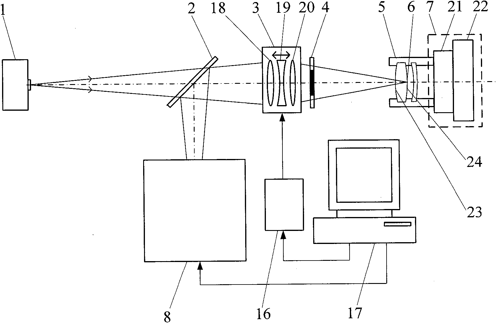
[0056] As shown in Figure 4 and Figure 7, the optical axis and gap measurement device of the differential confocal inner focusing method mirror group includes a point light source 1, which is sequentially placed in the first beam splitter 2 and the inner focusing The objective lens 3 and the annular pupil 4 also include a differential confocal system 8 placed in the reflection direction of the first beam splitter 2; the surface of the measured mirror group 5 and the first beam splitter 2 reflect the light beam to the differential confocal system 8, The second beam splitter 11 in the differential confocal system 8 divides the light into two paths, the reflected light illuminates the first light intensity sensor 9 located behind the focus, and the transmitted light illuminates the second light intensity sensor 10 located before the focus.

[0057] The device also includes an adjustment frame 7 , a main control computer 17 and an electromechanical control device 16 . The adjustme...

Embodiment 2

[0074] As shown in FIGS. 5 and 7 , the second embodiment can be formed by replacing the differential confocal system 8 in FIG. 7 of the first embodiment with the differential confocal system 8 of FIG. 5 . The difference from Embodiment 1 is that after the light enters the differential confocal system 8, the second beam splitter 11 divides the light into two paths, the reflected light illuminates the first light intensity sensor 9 after passing through the focused pinhole 12, and the transmitted light passes through The front pinhole 13 illuminates the second light intensity sensor 10 behind. All the other measuring methods and devices are the same as in Example 1.

Embodiment 3

[0076] As shown in FIGS. 6 and 7 , the third embodiment can be formed by replacing the differential confocal system 8 in FIG. 7 of the first embodiment with the differential confocal system 8 of FIG. 6 . The difference from Embodiment 1 is that after the light enters the differential confocal system 8, the second beam splitter 11 divides the light into two paths, and the reflected light forms an image on the surface of the first light intensity sensor 9 after passing through the focused microscopic objective lens 14. The transmitted light is imaged on the surface of the second light intensity sensor 10 after passing through the pre-focus microscopic objective lens 15; wherein the object plane of the back-focus microscopic objective lens 14 is positioned after the focus, and the first light intensity sensor 9 is placed on its image plane, and the pre-focus microscopic The object plane of the objective lens 15 is located in front of the focus, and the second light intensity senso...


PUM


Abstract

The invention relates to method and device for measuring an optical axis and a gap of a lens group by a differential confocal internal focusing method, belonging to the technical field of optical precision measurement. The method comprises the following steps of: firstly accurately regulating the optical axis of the measured lens group by combining an internal focusing objective with an autocollimation method; then realizing the high-accuracy positioning of each surface of the measured lens group by utilizing a differential confocal focus-fixing principle, and acquiring a numerical aperture angle of a differential confocal light cone positioned on each positioning point; finally sequentially calculating each gap of the measured lens group by utilizing a ray tracing recursion formula, and also leading an annular optical pupil into a measuring optical path to form a hollow measuring light cone so as to reduce the influence of astigmation on a measurement result. The invention combines a differential confocal technology with an internal focusing technology, has high measurement accuracy, high speed, simple system structure, long working distance, no need for disassembling the measured lens group in a measuring process, and the like and can be used for the non-contact high-accuracy measurement of the optical axis and the gap of the lens group.

Description

technical field [0001] The invention belongs to the technical field of optical precision measurement, and relates to a method and device for measuring the optical axis and gap of a mirror group by differential confocal inner focusing method, which can realize the non-contact of the optical axis and gap of the mirror group without disassembling the mirror group High precision measurement. technical background [0002] In the optical field, the measurement of the optical axis and gap of the lens group is of great significance. During the assembly process of high-performance optical systems such as lithography objective lenses and aerospace cameras, it is necessary to precisely adjust the lens gap, radial offset and optical axis deflection angle according to the optical axis, curvature radius and refractive index of the lens in the lens. Taking the objective lens of lithography machine as an example, the optical axis tilt or gap deviation of each single lens will cause spheric...

Claims


Application Information

Patent Timeline
IPC IPC(8): G01B11/14G01M11/02
Inventor 赵维谦邱丽荣史立波李雅灿孙若端沙定国苏大图
Owner BEIJING INSTITUTE OF TECHNOLOGYGY
Why Eureka
Try Eureka