
Photoetching machine projection objective wave aberration on-line detector and method

A technology of projection objective lens and detection device, applied in the field of optical detection, can solve the problems of difficult calibration, low spatial sampling frequency and wavefront sampling ability, inability to realize shearing interferometer shearing ratio, etc., so as to improve measurement speed and measurement accuracy , Improve sensitivity and measurement accuracy, and make up for the effect of low contrast of interference fringes

Active Publication Date: 2011-12-14
BEIJING INSTITUTE OF TECHNOLOGYGY
View PDF1 Cites 2 Cited by
  • Summary
  • Abstract
  • Description
  • Claims
  • Application Information

AI Technical Summary

Problems solved by technology

The main disadvantages of these two technologies are: in order to obtain the entire wavefront, it is necessary to convert the one-dimensional grating surface to achieve separate measurements in the x and y directions. On the one hand, the grating will introduce astigmatism during the conversion process, and it is difficult to calibrate. Thus affecting the measurement accuracy; in addition, the two measurements also have a certain impact on the measurement speed
On the other hand, it overcomes the shortcomings of Nikon's Shack-Hartmann wavefront sensing technology, such as small dynamic range, low spatial sampling frequency and low wavefront sampling ability.
However, the aforementioned four-beam shearing interferometer and orthogonal grating shearing interferometer are all based on the Talbot effect, and the detector can only be used when the distance between the grating and the grating is d=np 2 / λ collects the interferogram
Therefore, the disadvantages of these two technologies are: on the one hand, it is impossible to realize the continuously adjustable shear ratio of the shear interferometer.
It can be seen that when the exit pupil diameter of the objective lens to be tested is constant, the shear ratio is related to the period of the grating. In order to obtain the shear ratio required for different detection objects, gratings with different periods must be designed, and even if different periods are selected Grating is also difficult to achieve continuous adjustable shear ratio
On the other hand, from the Talbot distance formula d=np 2 It can be seen from / λ that in the short-wave field (such as 193nm), in order to realize the on-line detection of the wave aberration of the lithographic objective lens, the interferometer should have a high degree of integration, so the size of d has a certain limit
In this way, the period of the grating is required to be very small, and as a result, a large geometric coma will be introduced, which affects the detection accuracy

Method used


Image

  • Photoetching machine projection objective wave aberration on-line detector and method
  • Photoetching machine projection objective wave aberration on-line detector and method
  • Photoetching machine projection objective wave aberration on-line detector and method

Examples


Embodiment Construction

[0050] The present invention will be described in further detail below in conjunction with the accompanying drawings and specific embodiments.

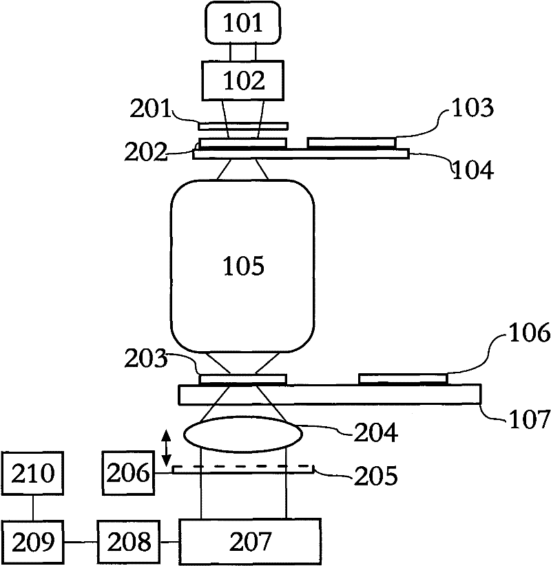
[0051] Firstly, the structural composition and working principle of the lithography machine are described. The lithography machine includes an exposure light source 101 , an illumination system 102 , a mask 103 , an object-space workpiece stage 104 , a projection objective lens 105 , a silicon wafer 106 and an image-space workpiece stage 107 . After passing through the illumination system 102, the light emitted by the light source 101 is illuminated on the mask plate 103, and the pattern on the mask plate 103 is projected onto the silicon wafer 106 coated with photoresist in a step-and-scan manner through the projection objective lens 105. Realize pattern transfer. The light source 101 is an ArF excimer laser with a wavelength of about 193 nm or a KrF excimer laser with a wavelength of about 248 nm. The illumination system 102 has a...


PUM


Abstract

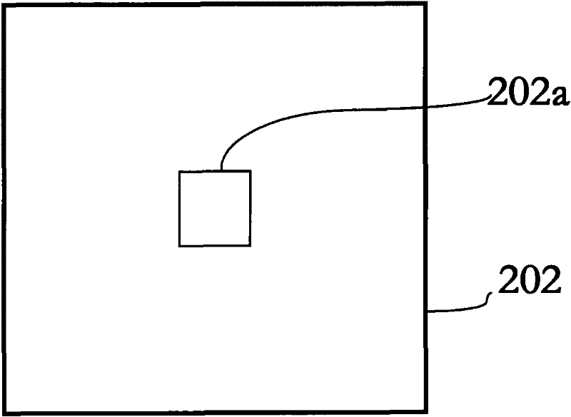
The invention discloses a photoetching machine projection objective wave aberration on-line detector and a method. A diffuser is integrated on an object space mask plate which is arranged on the object plane of a projection objective, fixed, supported and driven by an object space work piece table in the photoetching machine; an image space mask plate is arranged on the image plane of the projection objective, supported and driven by an image plane work piece table. A collimator objective is arranged after the image surface of the projection objective; and the focal plane of the object space of the collimator objective is coincided with the image plane of the projection objective. Shearing mechanism is arranged between the projection objective and a photoelectric detector. The invention can realize the continuous tunableness of the shear ratio and increases the measuring sensitivity and measuring accuracy; secondly, a square hole is used for expanding the light source, thus increasingthe utilization factor of the light intensity of the exposure light source, the measuring speed and measuring accuracy; and finally, the system error self-calibration technology can rapidly obtain the wave aberration of the projection objective with high precision.

Description

technical field [0001] The invention belongs to the field of optical detection, and relates to a high-resolution optical imaging system wave aberration online detection device and method, in particular to a projection objective lens wave aberration online detection device and method for high-resolution photolithography machines. Background technique [0002] As the mainstream technology of integrated circuit manufacturing, optical lithography technology plays an extremely critical role in improving the performance of integrated circuits and promoting the rapid development of the semiconductor industry. Since the 1960s, integrated circuits have been developing rapidly following the "Moore's Law" proposed by Gordon E. Moore, one of the founders of Intel Corporation. Development——Since the first lithography machine came out in 1987, the lithography exposure wavelength has experienced the evolution of 436nm (g-line), 365nm (i-line), 248nm (KrF), and 193nm (ArF); The engraving p...

Claims


Application Information

Patent Timeline
Patent Type & Authority Patents(China)
IPC IPC(8): G01M11/02G03F7/20
Inventor 李艳秋汪海刘克
Owner BEIJING INSTITUTE OF TECHNOLOGYGY
Learn More